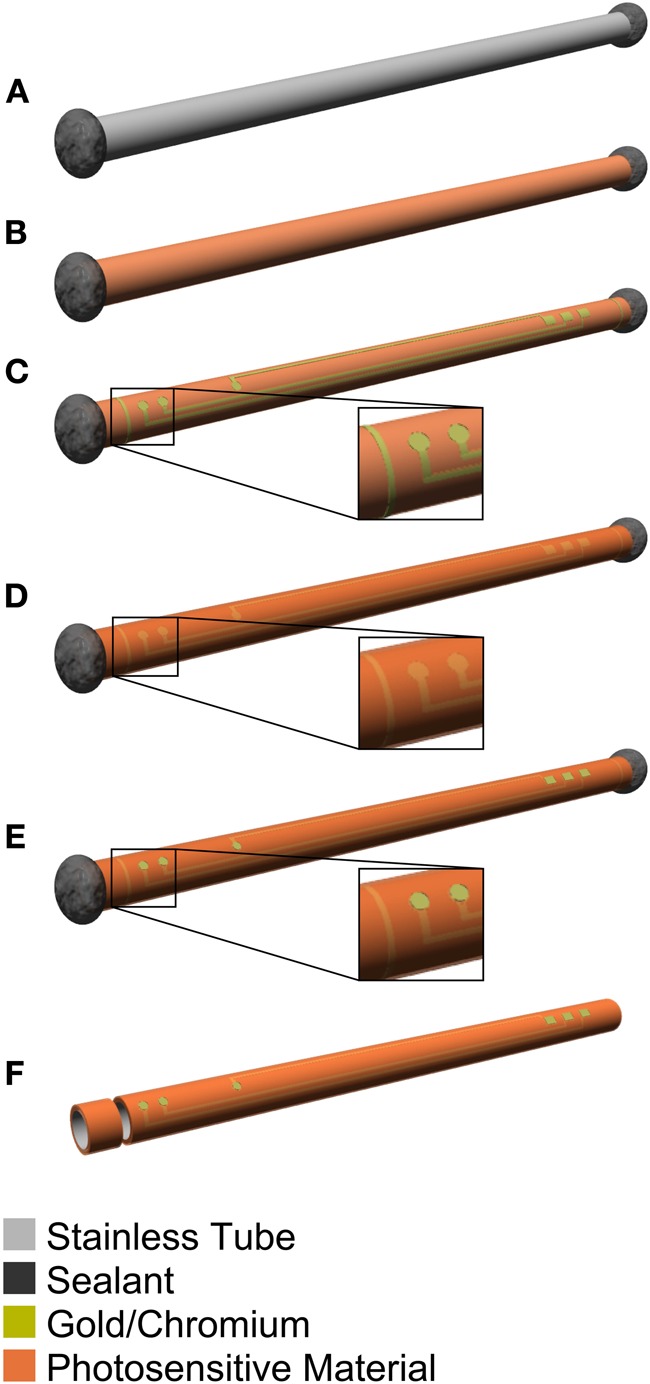
Figure 2.

Schematic diagram of the manufacturing process for the guide cannula electrode of the microdialysis probe. (A) The hole of the stainless-steel guide cannula is covered with epoxy. (B) Photosensitive-polyimide is deposited on the guide cannula. (C) Chromium/gold is deposited and recording microelectrodes, hard wiring, and slit are patterned. (D) Photosensitive-polyimide is deposited again. (E) Exposed recording microelectrode and connector sites are patterned. (F) The guide cannula is cut to the optimal length at the slit.
