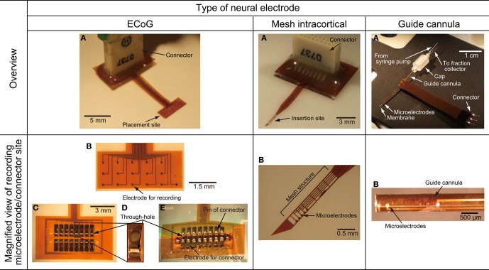
Figure 4.
Photographs of the fabricated ECoG electrode, mesh intracortical electrode, and guide cannula electrode of the microdialysis electrode. (A) Overview of the fabricated neural electrode. (B) Magnified view of recording microelectrodes or connector sites. (C) Back face of the connector side of the ECoG electrode. (D) Magnified view of a through-hole for connector pins in the ECoG electrode. (E) Back face of connector side fitted with soldering pins of connector in the ECoG electrode.

