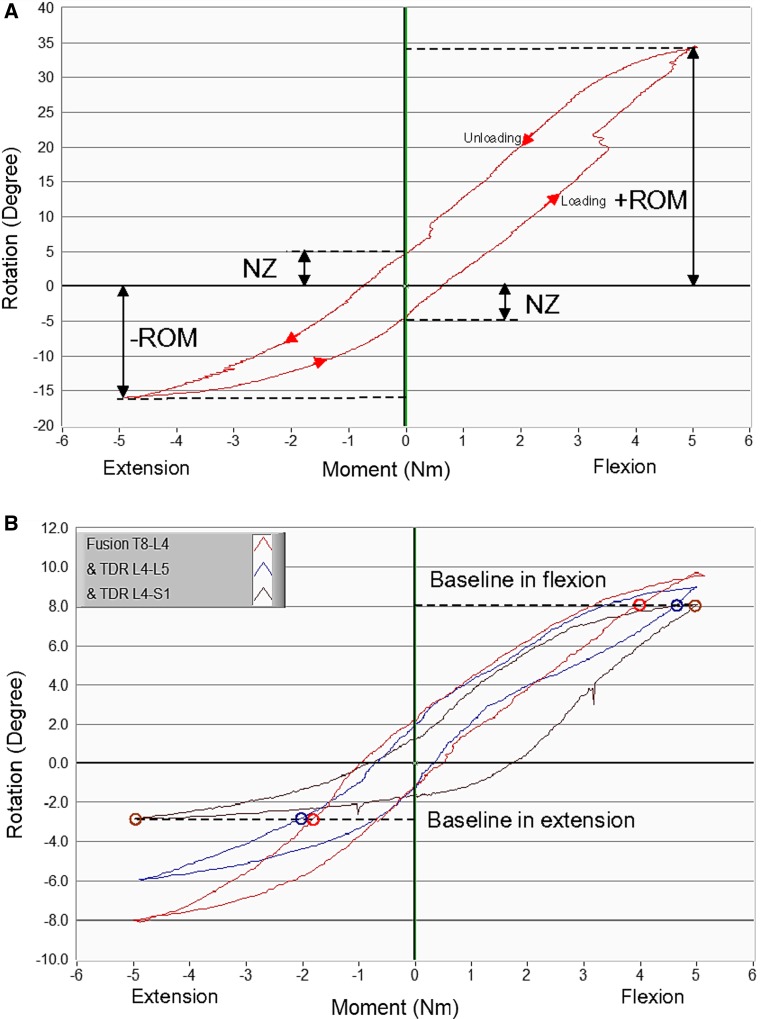
Fig. 3.
a Schematic of the T8–S1 rotation versus applied moment from the continuous flexibility test indicating the definition of Range of Motion and Neutral Zone. Note that in this figure +ROM and −ROM corresponding to the range of motion at the maximum and minimum applied moments.b An example of the modified hybrid flexibility–stiffness protocol analysis demonstrated on the T8–S1 total motion graph for the various surgical conditions. Baselines in flexion and extension are determined by the least motion in all surgical conditions tested at those directions (most leftward and rightward circled data points). The baseline moments corresponding to the baseline motions are determined for each condition (other circled points) and the kinematic parameters are subsequently analyzed at these baseline moments. MAV Maverick

