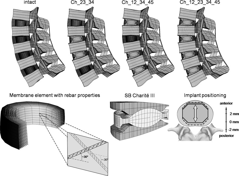
Fig. 1.
Top finite element models of the lumbar spine (L1–L5) showing the intact state and three different implantation scenarios: Ch_23_34, Ch_12_34_45 and Ch_12_23_34_45 (the abbreviations are explained in Table 1). Bottom left the collagen fibres were represented by membrane elements in conjunction with the rebar option simulating a direction dependent non-linear stress–strain behaviour. Bottom right finite element mesh of the SB Charité III disc and a schematic illustration of the investigated implant positions. The position was varied by 2 mm in both anterior and posterior directions

