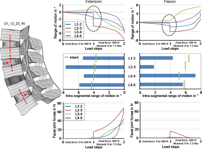
Fig. 7.
The progression of the intra-segmental range of motion during load application and the corresponding final values as well as the facet joint forces in relation to the load application in extension and flexion when using the Ch_12_23_45 model. The Charité disc was placed centrally in the L1–L2, 2 mm anteriorly in the L2–L3 and 2 mm posteriorly in the L4–L5. The dashed ellipse illustrates an instability during the follower load application

