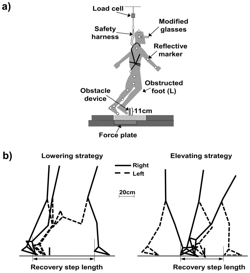
Figure 1.
a) Diagrammatic representation of the experimental setup, and b) definition of the recovery step length. a) The obstacle device consisted of an 11-cm tall plate, which lay flat on the floor during level walking and became upright when triggered by turning off the electromagnets. The trip was induced by obstructing the subject’s left limb (L) during the mid-to-late swing phase. All subjects wore a pair of modified glasses that blocked the lower half of the visual field. Twenty-seven light-reflective markers were placed on the subject and the obstacle device. The subject wore a safety harness that was attached to shock-absorbing ropes and was individually adjusted to prevent a fall to the ground. A load cell connected to the rope was used to measure the force exerted on the harness by the subject. b) The recovery step length for the lowering/elevating strategy was calculated as the horizontal distance measured from the most posterior position of the left/right heel marker during the stance phase of the left/right foot (prior to obstacle-hit) to the most posterior position of the right/left heel marker during the stance phase of the right/left foot after an obstacle-hit. The thick black vertical line represents the location of the obstacle device.

