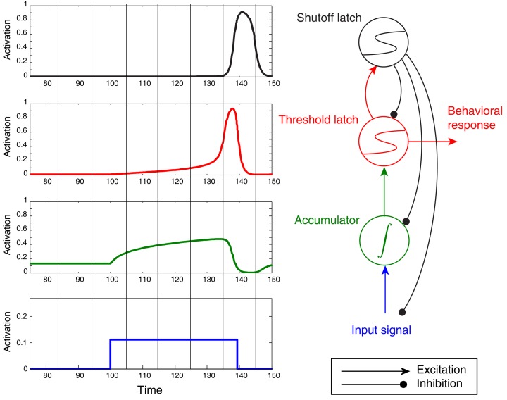
Figure 6.
Noiseless activation traces of a complete circuit comprising an accumulator/integrator, threshold latch, and shutoff latch, but lacking positive feedback from threshold-to-accumulator. Blue: input signal; green: accumulator; red: threshold latch; black: shutoff latch. Here the stimulus was arbitrarily terminated when the threshold latch exceeded 0.8 activation. Note the post-response dip below baseline in the accumulator.

