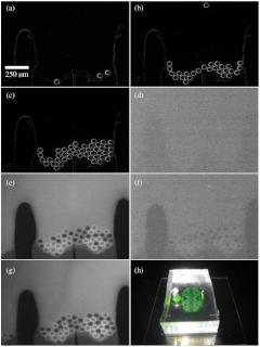
Fig. 5.
Prototype testing of the microfluidic chamber. (a–c) beads were loaded under phase contrast into the microfluidic chamber. Beads were blocked by the microfluidic barrier. (d) Switching to fluorescence imaging showed no fluorescence. (e) Fluorescein was flowed through channel. Beads appeared apparent in contrast to the background fluorescence. (f) Background fluorescence was washed out with distilled water. (g) Fluorescein was reintroduced into channel. (h) Image of final microfluidic chamber with fluorescein inside channels. The fluidic connections to the syringe pump are not shown.

