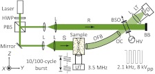
Fig. 1.
Schematic of the experimental setup. The component labels are defined as follows: HWP, half-wave plate; PBS, polarizing beam splitter; L, lens; S, signal beam; R, reference beam; UT, ultrasound transducer; OFB, optical fiber bundle; OC, optical condenser; BSO, photorefractive crystal; HV, high voltage electric field; BB, beam block; LT, lens tube; PD, photodiode detector; , system coordinates.

