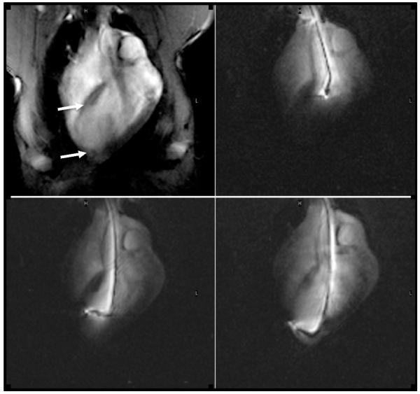
Figure 1.
MR fluoroscopic images show the navigation of the endovascular catheter in the ascending aorta (top left), LV chamber (top right) and the injections of a gene at two different infarct sites in this plan 5 weeks after infarction. The first image was acquired with external imaging coils showing the entire chest and the infarcted thin wall (arrows), while the latter three images were created with signal from the catheter showing the catheter shaft and tip.

