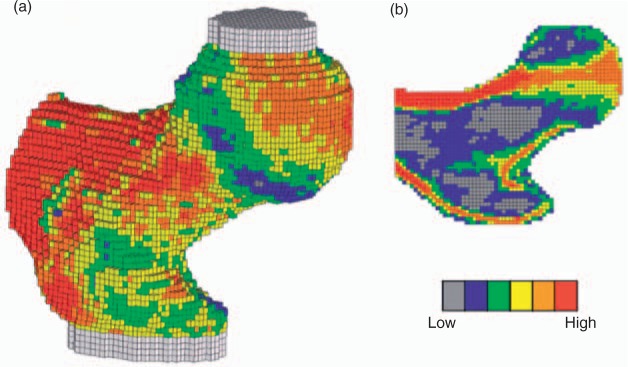
Figure 4.

Typical finite element [FE] model, showing 3D [a] and 2D sectional [b] views. The color coding shows the spatial variation of material strength assigned to the individual finite elements. The bone was oriented in a typical sideways fall configuration and shear-free loads were applied vertically through the molds covering the femoral head and greater trochanter, whereas moment and torque and axial force [but not shear force] restraint were applied to the distal end, just below the lesser trochanter [Keaveny et al. 2008).
