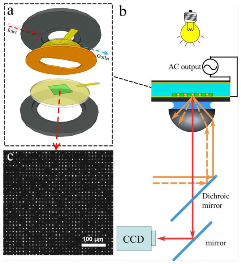
Figure 3.

(a) DEP cell assembly and (b) setup in an optical microscope. The microwell pattern (green) is fabricated on top of the Au-coated glass cover slip (yellow). A sample is sealed with an elastomeric gasket (orange) against Au-coated electrode (yellow) and both are connected to a function generator via copper foil (rectangular yellow pieces). (b) The illumination in transmission mode helped to identify the edges of the microwells. CCD camera captures fluorescent images of the probes from a commercial TIRF setup integrated with a 638 nm laser. (c) Microscope image (10×) of the fluorescent probes assembled inside the microwells.
