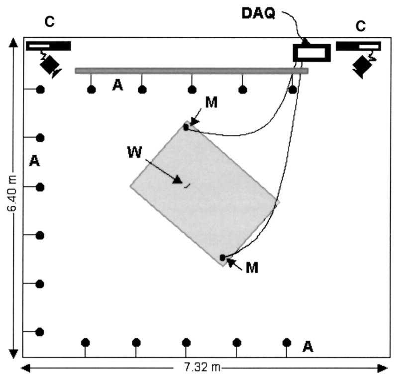
FIG. 2.

Plan view of flight room and array layout. A: microphone array, M: Ultrasound Advice microphones, C: High speed digital video cameras running at 240 frames per second, DAQ: Data Acquisition systems; IoTech WaveBook, 2 channels at 250 kHz each and National Instruments AT-MIO-16-E-1 board, 16 channels at 20 kHz each, W: Tethered worm. Shaded area represents the calibrated space (within which the path of the bat may be accurately reconstructed from the camera views).
