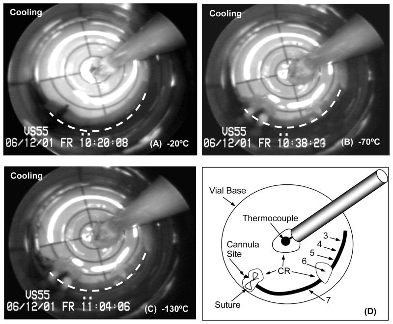
Figure 3.
Representative cryomacrographs of a 25mm-long carotid artery segment vitrification using low cooling and warming rates. The vessel centerline is represented by a dashed white line. Panel (D) shows a schematic diagram of the cryomacrograph in (C). In Panel (D) rings tested for mechanical function post-vitrification are labeled from 3 to 7 starting at the artery free-end. Rings #1 and #2 were cut prior to vitrification and served as fresh-control rings during mechanical testing. Vessel extremity inclusive of the suture up to the site of the original cannula tip location within the artery was removed prior to ring sectioning (Panel D). The location of ice crystallization (CR) in relation to the assignment of rings for subsequent testing is indicated on the Panel (D) schematic.

