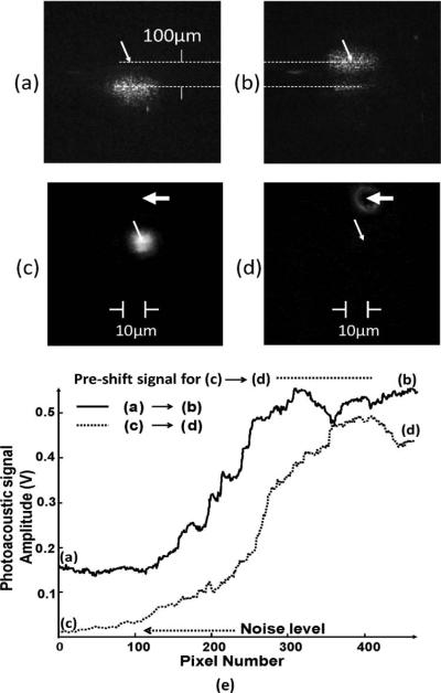
Fig. 2.
Profiles of laser beam as viewed through the carbon tape (a) before and (b) after being guided to the focus of the ultrasound transducer (marked by the arrows) by wavefront shaping. (c) Photo of graphite particle (marked by wide arrow) after being shifted to 10μm from the laser beam. (d) Refocused laser beam centered at the graphite particle after phase shaping. The narrow arrows mark the locations of the center of ultrasonic focus. The diameter of the ultrasound focus is 90 μm. (e) Time evolution of the amplitudes of the photoacoustic signal as the deformable mirrors undergo three iterations of phase shaping, each iteration scanning through 140 pixels. Also shown is the preshift signal level.

