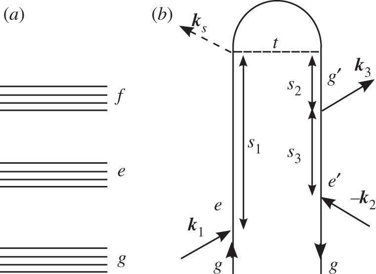
Figure 1.

(a) A generic level scheme for the experiments considered here. (b) A closed-time path-loop diagram for a four-wave mixing experiment. The loop describes the propagation of the wave function by moving clockwise, first forwards in the left branch and then backwards in the right branch.
