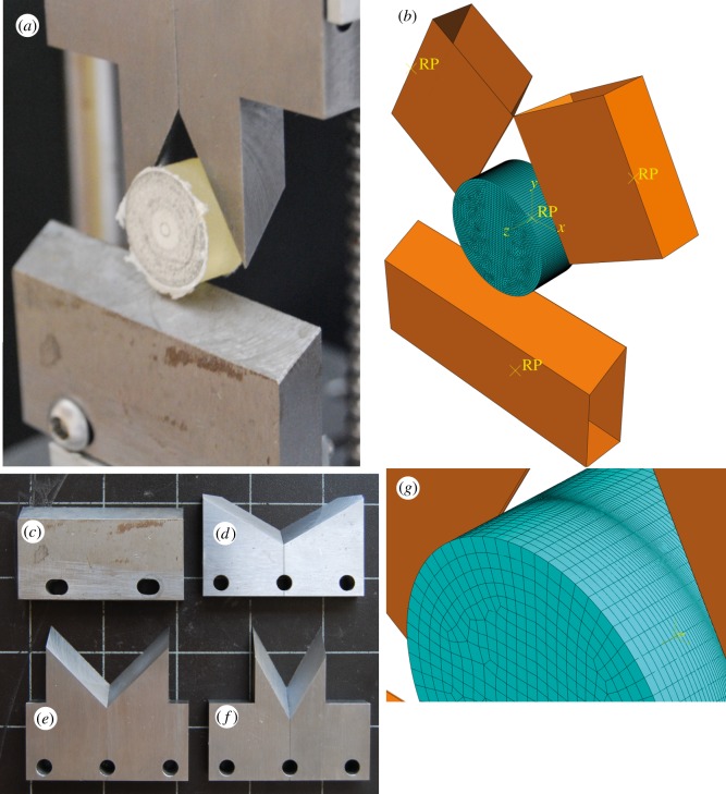
Figure 1.
Comparison of the physical experiments and computational model design. (a) Double guillotine testing device shown with a 2 cm wide, 1 cm deep cylinder of a photoelastic resin of known material properties. (b) FE model replicating the physical experiment. The meshed portion represents the photoleastic material, while the orange analytically rigid shapes represent the steel blades. The yellow RP points are reference points used by the model to control movement of the various parts. (c–f) Blade tools used for the physical experiments. (c) Straight edge tool. (d) Blade tool set at a 120° notch angle. (e) Blade tool set at a 90° notch angle. (f) Blade tool set at a 60° notch angle. All blades have a 30° rake angle. (g) Close-up of the mesh of the FE model, illustrating the adaptive nature of the mesh, with a higher density of elements along the region where contact between blade object and mesh is made.

