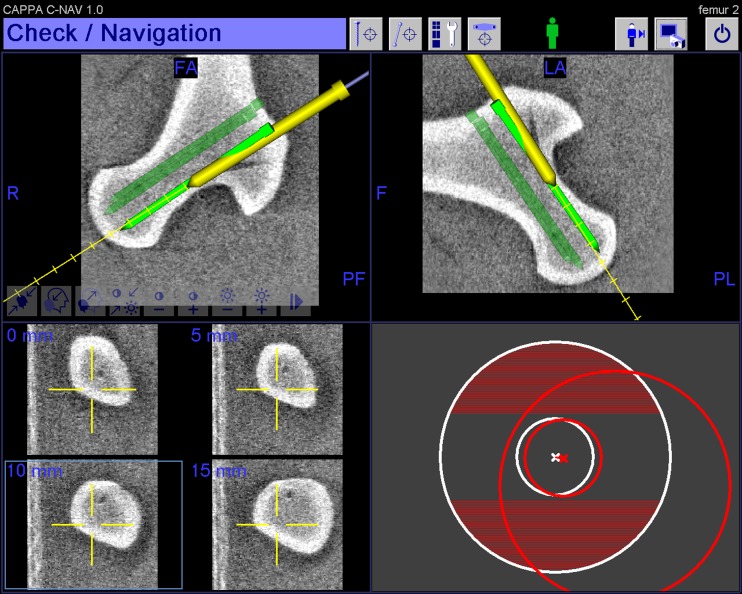
Fig. 3.
Visualisation of the image-guided freehand navigation of the guide wire in the planned trajectory. Display of two cross-hair-like vectors for orientation of the navigation tool on the right lower part of the display. The small, inner circle represents the position of the guide wire tip; the larger, outer circle represents the position of a point on the guide wire axis. The inner and the outer circle in the centre means that the tool is aligned. Note the representation of the depth of the distance ahead of the guide wires tip on the left lower part of the display

