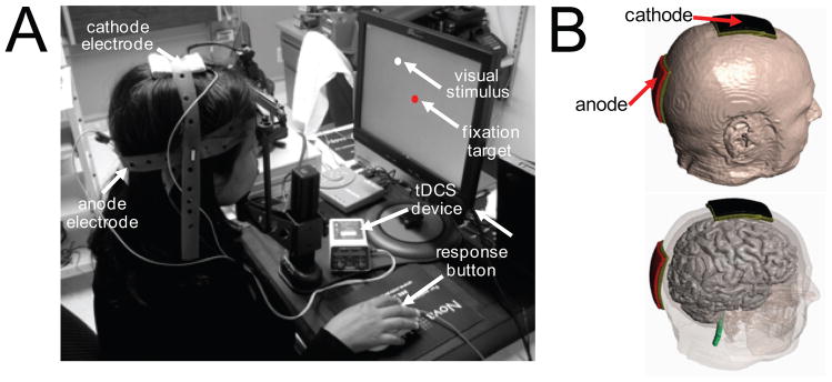
Figure 1.
Experimental set-up demonstrating combination of tDCS montage with VRT. (A) For VRT, the patient is seated in front of a computer screen and instructed to fixate upon a central fixation target and respond (using button press) to the detection of visual stimuli. For both active and sham tDCS, a montage consisting of an anodal electrode (placed over the occipital pole; Oz) and cathodal electrode (placed over the vertex; Cz) is used. (B) Three dimensional head and montage renderings illustrating the relative location of the anodal and cathodal tDCS electrodes.

