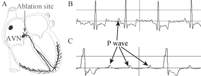
Figure 2. Atrioventricular conduction block after AVN ablation. (A): A schematic diagram of the area usually ablated for creation of complete atrioventricular conduction block; (B): Typical tracings of canine electrocardiograms (Lead II) of the sinus node rhythm; (C) The rhythm of complete atrioventricular block after ablation. The ventricular escape rhythm shows the typical wide QRS complex (C) after AVN ablation with a radio frequency energy catheter. AVN: atrioventricular node.

