
Fig. 2.
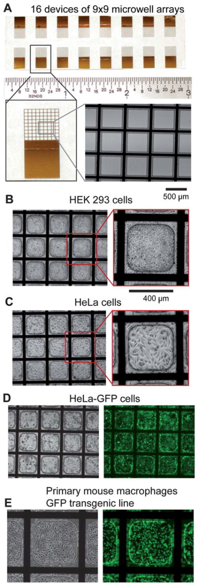
Microwell array design and biocompatibility. A) Top-Image of a complete, fabricated microwell array on ITO-coated glass slides. Sixteen devices consisting of a 9 × 9 microwell array each are spaced for dicing and individual experimentation. Lower left-Image of a single device. Lower right-Magnified image of a microwell array where the opaque (black) areas are the patterned titanium/gold electrode grid and the insulating microwell material surrounding the grid made of SU-8. B) Image of HEK 293 cells, C) HeLa cells, and D) HeLa-GFP cells cultured in microwell arrays 48 h post-seeding. E) Primary mouse macrophages derived from a GFP transgenic mouse line cultured and imaged in phase (left) and fluorescence (right) in a microwell array.