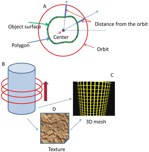
Figure 2.
Schematic of the MT method to construct the 3D shape of the object. (A) As the laser beam goes around the structure, the local modulation function gives the distance of the surface from the average orbit. This distance is calculated at several angles giving a polygon which approximate the shape of the surface at the orbital plane. This polygon is then interpolated to 128 points to produce a smooth line. (B) The orbital plane is then moved along the cylinder axis. For each plane we produce a polygon. (C) The stack of polygons provides a mesh which represents the 3D structure of the object. (D) The 3D mesh is covered by a texture given by specific quantities such as the fluorescence intensity or the intensity ratio of two channels.

