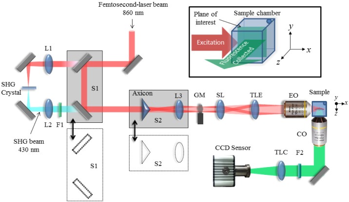
Figure 1.
Schematic diagram of our DLSM setup. The translation stage S1 allows switching between linear DSLM, where the beam pass through the SHG crystal and lenses L1 and L2, and 2p-DLSM where the femtosecond-laser beam pass unmodified. Gaussian or Bessel beams are selected by moving the translation stage S2 that contains an axicon and the Fourier transforming lens L3. A galvo mirror GM, a scan lens (SL), a tube lens (TLE) and an excitation objective lens (EO) are used to create the light sheet with the desired properties at the sample plane. The fluorescence generated in the sample is collected at 90 degrees by a collection objective lens (CO) and a regular tube lens (TLC) that forms image onto the CCD sensor with the designed magnification. Filters F1 and F2 are used to cut off the excitation light from the fluorescence images collected. The inset (top-right) shows the excitation-collection geometry that defines the notation of the axes used in this work.

