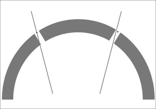
Figure 5.

On the left of the figure the intended trajectory has been marked on the outer table of the skull (small black dot) and the “burrhole” centred on this point. This method does not take into account that the burrhole trajectory is orthogonal to the outer table and differs to the planned trajectory. As a result, the edge of the inner table obstructs the intended trajectory. On the right of the figure, the burrhole was placed slightly lateral to the intended trajectory (small black dot). This adjustment allows the planned trajectory to traverse the burrhole unimpeded by both outer and inner bone margins
