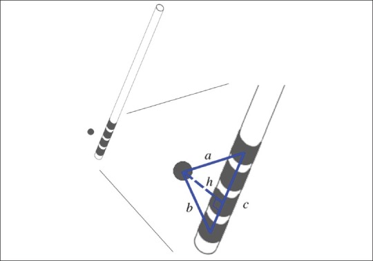
Figure 7.

Calculation of the stereotactic targeting error in a DBS procedure: the planned target point is shown in relation to the actual quadripolar lead location. The centres of the deepest and most superficial DBS contact and the intended target point form a triangle in space (depicted in blue with sides a, b and c). The perpendicular distance between planned target point and electrode trajectory (h) is defined as the stereotactic targeting error
