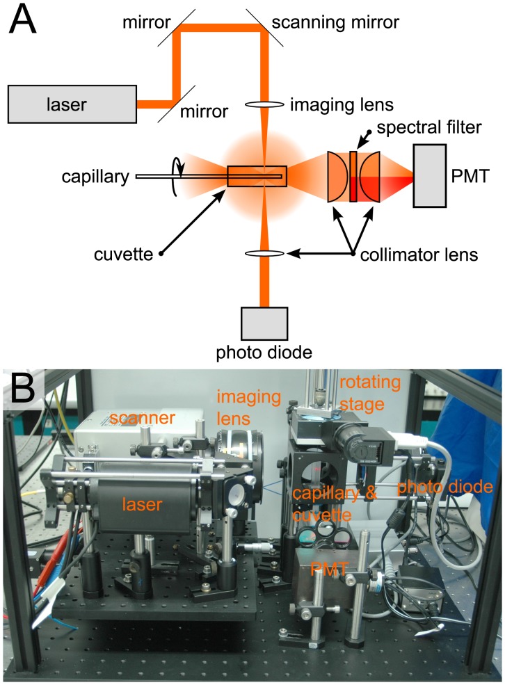
Figure 1. Scanning Laser Optical Tomography setup.
Schematic drawing (A) and photograph (B) of the Scanning Laser Optical Tomograph. A laser beam is directed via two mirrors onto an x-y-galvanometer-scanning system. The system is placed in the back focal plane of the imaging lens, which produces a weakly focused beam in the imaging volume. Transmitted light collected with a collimating lens onto a photo diode. Scattered and fluorescent light is collimated with a lens at the bottom of the cuvette. A spectral filter suppresses the scattered light for fluorescence detection (indicated in red; in A) or the fluorescent light for scattered light detection (indicated in orange; in A). The filtered light is then collimated onto a photomultiplier tube (PMT). A capillary containing the sample is rotated within the cuvette which is filled with glycerol.

