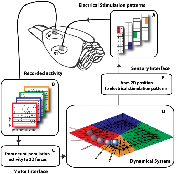
Figure 1. Experimental setup of the dynamic neural interface.
We placed two 16-channel microwire arrays (recording and stimulating arrays) in the vibrissa motor (M1) and sensory areas (S1) of a rat brain cortex. (A) In this example 4 electrical stimulation patterns are set by specifying the pair of electrodes in the 16-channel microwire stimulating array placed in area S1. (B) The activity of a small population of single neurons (11 in this illustration) of area M1 is recorded in response to each electrical stimulation pattern. The activity of each neuron is plotted on a row over a rectangular frame, whose color indicates the correspondence with a stimulation pattern. (C) The motor interface generates a force vector from the first two principal components of the response of the M1 neurons. (D) The obtained force vector is applied to a simulated point-mass moving in a viscous medium. The interaction with such dynamical system aims to emulate a reaching movement creating a convergent force field similar to the force fields observed during microstimulation of the spinal gray matter. (E) The sensory interface maps each point in the field into the corresponding stimulation pattern.

