
Figure 2.
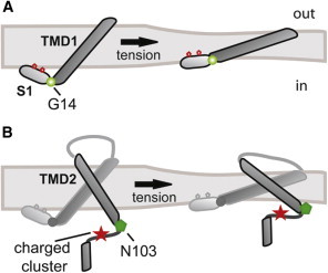
Schematic representation of the interactions between MscL TMDs and the lipid membrane. (A) TMD1 and the N-terminal helix (S1) are represented in the closed (left) and open (right) states. The position of Gly-14 between the S1 and TMD1 domains is shown as a green sphere. The conserved phenylalanine residues at positions 7 and 10 in the S1 domain are shown as red hexagons. (B) A single MscL subunit is represented in closed (left) and open (right) states. TMD2, the cytoplasmic loop, and the C-terminal helix are highlighted in a darker color. The positions of residue N103 and the charged cluster (RKKEE) are shown as a green hexagon and a red star, respectively.