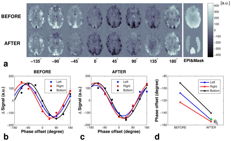
FIG. 3.
(a) PCASL Prescan images of an example slice after pair-wise subtraction acquired at different phase offset θ before (top left row) and after (bottom left row) applying additional Gx/Gy for off-resonance compensation. The raw EPI image (top right) and ROI masks (bottom right) are shown on the right. (b) Average signal and fitted cosine curves from the left, right and bottom perfusion territories (b) before and (c) after applying additional Gx/Gy for off-resonance compensation, and (d) optimum phase offsets θm before and after applying the compensation gradients. θc is the calculated compensation phase offset (circle).

