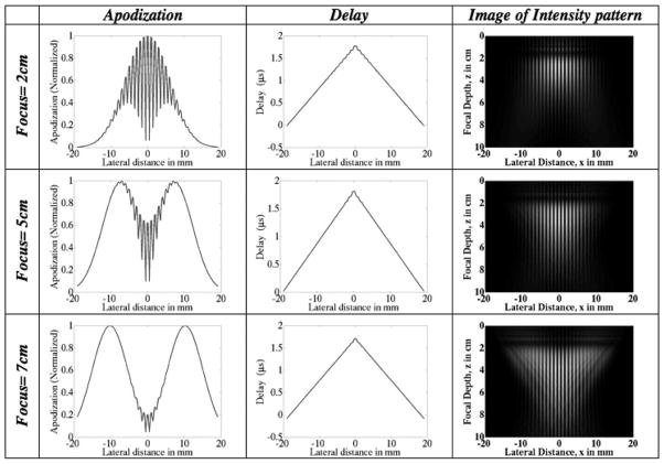
Fig. 6.
Intersecting plane wave method: plots of the transducer apodization and delay profiles at different focal depths for a fixed ROI envelope spread (lateral width) of 5 mm. The focal depth increases from top to bottom. (Left) The apodized beams are pushed further apart to create the ROI at greater depths. (Middle) The delay that is applied across the aperture elements to steer the beam according to the desired depth. The delay profiles do not vary significantly with increasing focal depth because the spatial frequency is kept constant. (Right) Image of intensity pattern.

