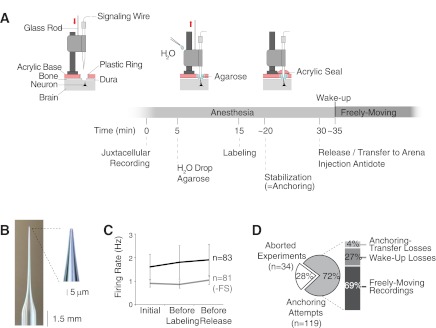
Fig. 2.
Steps and performance of the juxtacellular recording technique in freely moving animals. A: schematic representation of the steps to perform juxtacellular recordings in freely moving animals. Time 0 refers to the initial establishment of the juxtacellular configuration. Note that the “agarose” step can also be performed before, and not necessarily after, establishing the juxtacellular configuration. Components modified from Burgalossi et al. (2011), with permission from Elsevier. B: recording electrode with long thin taper used for juxtacellular recordings. Inset: higher magnification of the tip. C: average firing rates computed during the 1st minute of juxtacellular recording (“initial”), “before labeling,” and “before release” of the animal from the head-fixation frame. The averages are calculated separately for all neurons (n = 83, black) and without the 2 fast-spiking cells (−FS) in our data set (n = 81, gray). Error bars represent SD. D: overview of the performance of the friction device for obtaining juxtacellular recordings in freely moving animals: 28% of the experiments were interrupted because of inability to obtain stable juxtacellular recordings (“aborted experiments”); the percentages for “anchoring-transfer losses,” “wake-up losses,” and “freely moving recordings” refer to the subset of experiments (72%) in which 1 stable juxtacellular recording in the target region was obtained and stabilization was attempted by application of acrylic (“anchoring attempts”).

