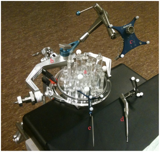
Figure 6. Drill Tracking Accuracy Experimental Setup.
The setup in the operating room during drill tracking accuracy experiments on the cylinder and ball phantom (a) is shown. Note the head clamp (b) and reference frame (c). Registration of the phantom was performed via four rigidly attached screws that served as fiducial markers. The top of the cylinders were touched with the drill (d) with attached tracking frame and pointer (e) and the image coordinates were recorded and compared with the actual positions to yield target registration errors.

