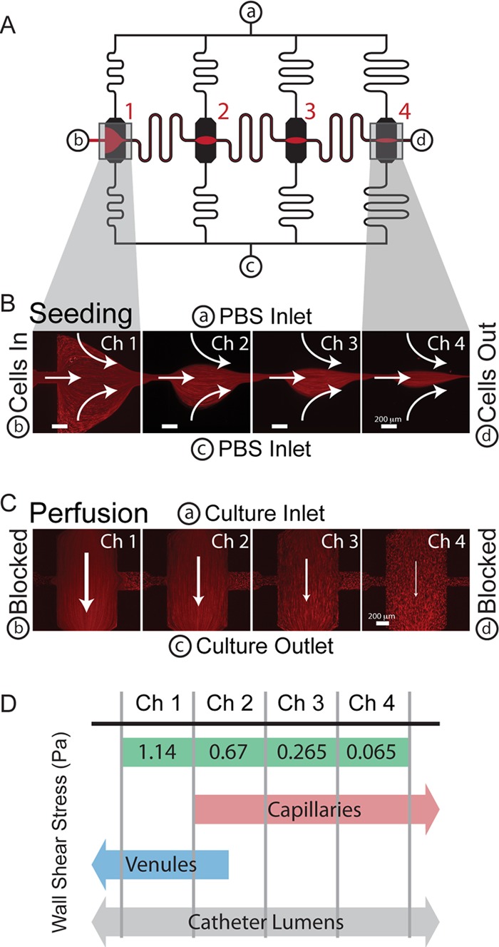
Fig 1.

Schematic and operation of the microfluidic biofilm assay. (A) The microchannel design consists of 4 parallel channels (black) with culture chambers placed halfway between inlet a and outlet c. These are connected by a seeding channel (red and black) from b to d. (B) Prior to shear culture, cells are seeded in the device by creating pinched flow in each chamber. (C) Subsequently, b and d are blocked, and the channels are converted to perfusion mode, in which chamber 1 (Ch1) has the lowest resistance and highest wall shear stress. There is significantly lower flow in the seeding channels per the design of the device. Red streaks in panels B and C are 1-μm fluorescent polystyrene beads in flow. (D) The wall shear stress spans over an order of magnitude in a single experiment, covering ranges seen in capillaries and venules as well as those calculated for catheter lumens. Shear stresses presented are for an inflow of 18 μl/min.
