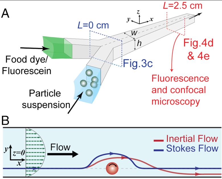
Fig. 3.
Schematic of the device and particle-induced convection. (A) Schematic of the device (w × h μm) used for microscopy. Particle suspensions are coflowed with a fluid stream containing dyes. High-speed, fluorescence and confocal microscopy images are captured at different points along the channel to characterize the transverse transport. (B) Schematic of the motion of fluid around the rotating particle in Stokes and inertial flow at z = 0. For Stokes flow the streamlines (blue line) behave symmetrically. However, for the inertial flow (red line), the path of the fluid is diverted towards the particle, resulting in a lag upstream and finally the return of the fluid elements closer to the particle than the Stokes-predicted (blue) path.

