Fig. 8.

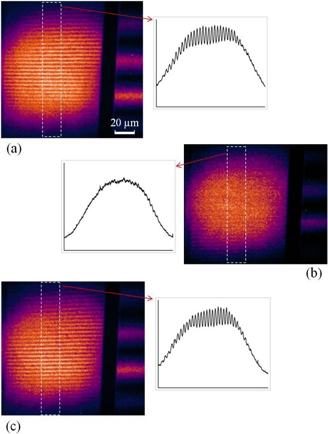
X-ray reflective interferometer demonstration of compensating for a small pitch angle difference between the G0 and G1 gratings by moving the detector phosphor screen. (a) In the initial setup, the image on the detector screen consists of the primary interferences fringes on the left, and large-period secondary fringes (alignment aids) on the right margin. The intensity profile of a center cross-section of the primary fringes is shown. The fringe visibility as defined in the text is 12.3%. The scale bar indicates 20 µm in the vertical direction perpendicular to the x-ray beam. (b) After making a small change of the G1 pitch angle, the primary fringes are obliterated. (c) Moving the detector screen by 4.2 cm along the x-ray beam axis recovers the primary fringes, and the fringe visibility returns to 12.9%. The movement distance indicates that the the pitch angle change we introduced was 0.19 milliradians (39 arc seconds).
