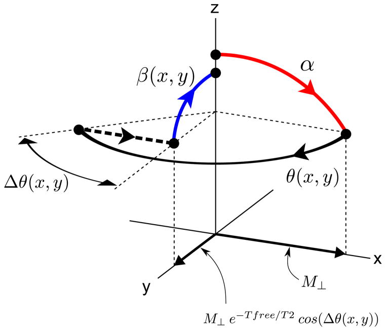
Figure 4.
Graphical illustration of the rationale behind Eq. [2]. Immediately after the tip-down pulse α, the transverse signal component has magnitude M⊥ and is aligned with the axis of the tip-down pulse (x). During the free precession interval, the transverse component is reduced to M⊥ e−Tfree/T2 (not indicated in the figure). We then assume that there is a mismatch Δθ between the transverse spin phase and the phase of the tip-up pulse. As a result, only the component of M⊥ e−Tfree/T2 along the axis of the tip-up pulse, i.e. M⊥ e−Tfree/T2 cos(Δθ), is tipped back up. Equation [2] is obtained by defining an effective transverse relaxation rate T2eff defined by the relation M⊥ e−Tfree/T2 cos(Δθ) ≡ M⊥ e−Tfree/T2eff.

