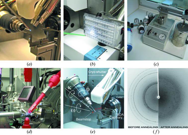
Figure 7.
Ancillary facilities of the MX beamlines. (a) UV-RIP set-up on BL14.1. The crystal which is exposed to UV irradiation can easily be seen owing to its fluorescence, (b) In situ crystal screening of 96-well plates centred within the X-ray beam of BL14.1. (c) Noble gas pressure cell for Xe and Kr derivatizations (http://www.hamptonresearch.com/). (d) HC1c dehydration device mounted on BL14.3. (e) Cryo-shutter annealing device at BL14, with microdiffractometer MD2 and mini-κ MK3. (f) Results from the cryo-shutter operation (the device mounted on all beamlines); the image shows a diffraction pattern before (left) and after (right) cryo-annealing.

