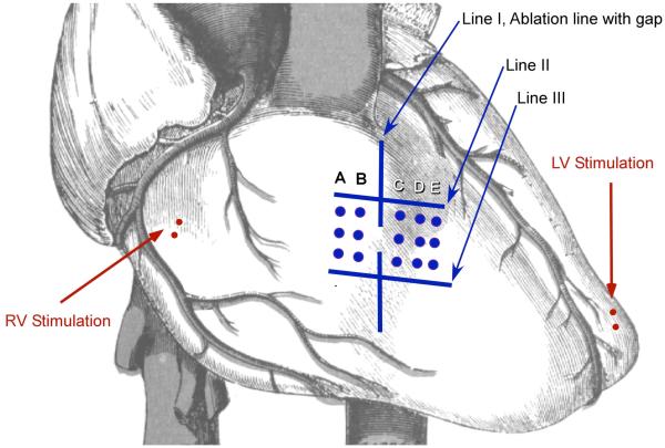
Figure 1.
Experimental set-up. Line I: Experimental ablation line with a gap. The gap length was decreased until there was no conduction across the gap. Line II and III: These are ablation lines created prior to Line I and oriented perpendicularly to the experimental line (line I). An electrode array with bipoles (columns A to E) was used to record local electrograms.

