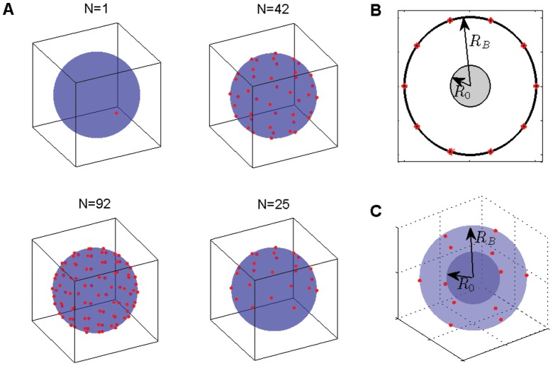
Figure 8. Placement of targets.
(red objects) on the boundary of a sphere. In the top left corner of panel (A), a single target is displayed. In the top right and bottom left corner of panel (A) 42 and 92 targets are placed according to a geodesic grid. In the bottom right corner of panel (A), the geodesic grid for 25 targets is used but only to half of the sphere. The fourth panel shows 25 targets on the upper hemisphere – to study localized activation of needle complexes. (B) If we have no information about the starting location of a random walker in a disk, we assume that it is uniformly random within a smaller disk of radius  . (C) The same idea applied to a random walker in a sphere; we assume that it can start anywhere within a smaller spherical volume of radius
  .
.

