
Figure 1.
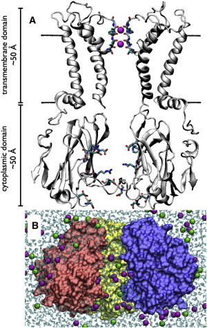
Kir channel structure and simulation setup. (A) The full-length Kir2.1/IRK open model. The two opposing positioned subunits of the transmembrane (I and III, residues 57–184) and cytoplasmic (II and IV, residues 185–350) domains are shown to reveal the ion permeation pathway. (Black line) Position of the membrane. The selectivity filter backbone atoms, including the K+ ions (magenta spheres), are shown explicitly. Side chains of residues in the cytoplasmic domain that are strong contributors to the electrostatic environment inside the pore of Kir2.1/IRK are also shown (E224, R228, D247, D255, D259, R260, and E299). (B) A snapshot of the all-atom, solvated open model of the Kir2.1/IRK cytoplasmic domain simulation system with ∼1 M KCl. (Magenta) K+ ions. (Green) Cl− ions. (Cyan) Water molecules. One of the subunits has been removed to show water and ions inside the pore.