
Figure 1.
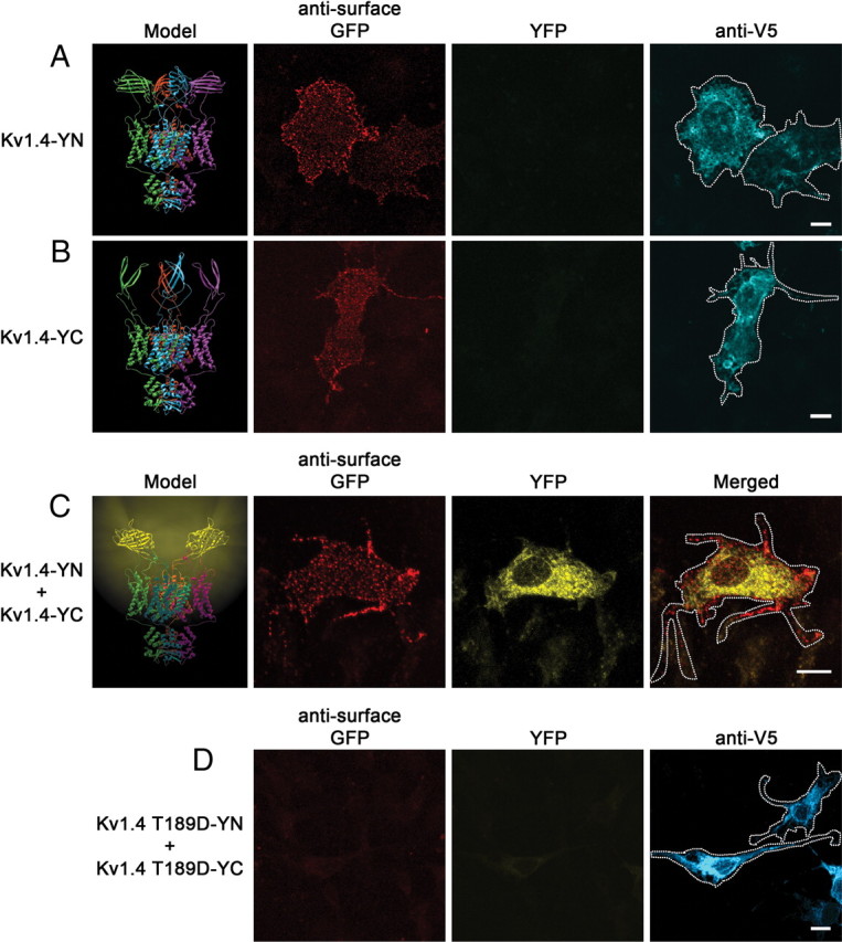
Tetramerization of tagged Kv channel subunits allows bimolecular fluorescence complementation. Model of Kv channel bimolecular fluorescence complementation shown on left. A–C, Ribbon diagrams depicting Kv1.4 with extracellular N-terminal half (Kv1.4-YN) or C-terminal half (Kv1.4-YC) exhibit no fluorescence, while that with the complemented fluorophore (Kv1.4-YN plus Kv1.4-YC) exhibits yellow fluorescence. Individual α-subunits are shown in cyan, purple, green, and red. Representative confocal images of COS-7 cells transfected with Kv1.4-YN (A), Kv1.4-YC (B), or Kv1.4-YN plus Kv1.4-YC (C) are shown to the right of models. Live-cell labeling of surface channel is shown on the left (red) (note the ability of the GFP antibody to recognize both fragments of YFP). YFP fluorescence is shown in the middle (yellow), and V5 immunostaining of permeabilized cells (cyan; A, B) or merged image (C) is shown on the right. D, Representative confocal images of COS-7 cells transfected with Kv1.4 T189D-YN plus Kv1.4 T189D-YC. Live-cell labeling of surface channel is shown on the left (red), YFP fluorescence is shown in the middle (yellow), and V5 immunostaining of permeabilized cells demonstrating channel expression is shown on right (cyan). Scale bars, 10 μm. Cell outlines are shown on merged image.