Abstract
Intra-cavity imaging coils provide higher signal-to-noise than surface coils, and have the potential to provide higher spatial resolution in shorter acquisition times. However, images from these coils suffer from physiologically-induced motion artifacts, since both the anatomy and the coils move during image acquisition. We developed prospective motion correction techniques for intra-cavity imaging using an array of tracking coils. The system had <50ms latency between tracking and imaging, so that the images from the intra-cavity coil were acquired in a frame of reference defined by the tracking array rather than by the system’s gradient coils. 2D Gradient-Recalled (GRASS) and 3D ECG-gated Inversion-Recovery-Fast-Gradient-Echo (IR-FGRE) sequences were tested with prospective motion correction using ex-vivo hearts placed on a moving platform simulating both respiratory and cardiac motion. Human abdominal tests were subsequently conducted. The tracking array provided a positional accuracy of 0.7±0.5mm, 0.6±0.4mm, and 0.1±0.1mm along the X, Y and Z directions at a rate of 20 frames-per-second. The ex-vivo and human experiments showed significant image quality improvements for both in-plane and through-plane motion correction, which although not performed in intra-cavity imaging, demonstrates the feasibility of implementing such a motion correction system in a future design of combined tracking and intra-cavity coil.
Keywords: intra-cavity coil imaging, prospective motion correction, cardiac MRI, tracking coils
Introduction
Intra-cavity imaging coils have been developed to improve signal-to-noise ratio (SNR) for internal organ imaging. The close proximity of small intra-cavity coils to the target organ increases the local SNR as compared to larger and more distant external surface coils. This increase in SNR can be used to generate higher spatial resolution and/or shorter acquisition times. Various intra-cavity imaging coils have been previously described including: intravascular coils used for cardiac and arterial wall imaging(1–5), endo-rectal coils used for prostate imaging(6,7), and intra-vaginal coils used for cervix and ovarian imaging(8,9). The images acquired with these intra-cavity coils are frequently superior in diagnostic and interventional imaging applications as compared to surface coils.
Intravascular catheter-based receiver coils have been developed for high resolution imaging of the heart and vascular walls (2,10–13). However, it has been difficult to achieve good image quality in vivo using such coils, due to the motion of the coil in the vessel’s blood stream or in concert with the vessel-wall’s motion. Efforts have been made to stabilize the coil relative to the imaging target. Martin (14) designed a coil incorporating a 9mm diameter “bullet tip” on the end of the coil to restrict coil motion relative to the vessel wall. The resulting images showed substantial improvements, but the mechanical rigidity of the “bullet tip” is not acceptable for clinical use. Expandable intravascular catheter coils have also been developed (5,12,15). These coils are folded during deployment and expanded once the target vessel is reached, contacting the wall and thereby minimizing the relative motion between the coil and the vessel wall. However, motion artifacts remain a major issue during high-resolution imaging since vessel wall motion causes the coil to move relative to the magnet’s frame of reference (12). Similarly, for the widely-used Medrad (Warrendale, PA) prostate endo-rectal MRI coil, an inflatable balloon is utilized to stabilize the position of the coil inside the rectum (7,16–18). The concave balloon ensures tight seating against the rectal wall at the level of the prostate. However, gross patient motion during the scan, as well as respiratory motion of the anterior abdominal wall and peristaltic bowel movements, can produce significant motion artifacts as compared to body array imaging (19). Thus, it has become apparent that motion correction techniques are required for intra-cavity coil imaging, so that the gain in SNR afforded by the coil is not compromised by motion artifacts.
MRI motion-artifact correction methods fall into two main classes: Retrospective and Prospective. Retrospective motion correction addresses motion artifacts following the acquisition of a complete set of raw image data, but before image reconstruction occurs. The raw data is corrected based on motion information derived from the images themselves, or based on motion probes, such as navigators (20). Retrospective corrections are less demanding on the system, and frequently work well for in-plane motion, but they are generally inadequate for through-plane motion, since T1-relaxation modulation perturbs image quality. To avoid these issues, Prospective motion correction techniques have been proposed, traditionally based on navigators (21–24). These techniques track motion during data acquisition and then rectify the acquisition position and orientation in real-time by adjusting MRI sequence parameters, to ensure the entire scan is acquired in the anatomy’s frame of reference rather than that of the gradient coils. However, in order to correct motion for high-resolution intra-cavity coil imaging, the navigator needs to have an accuracy of the same order of magnitude as the resolution of the intra-cavity coil image.
Stereoscopic cameras have been used for head surface movement tracking (25), but they cannot be used for tracking the movement of an intra-cavity coil within the body’s interior. Miniature (mm diameter) radio frequency (RF) coils, together with the MR-tracking techniques, have been used as active markers for motion detection in diagnostic and interventional MRI (26–28), and have demonstrated sub-millimeter spatial accuracy and 20 frames-per-second (FPS) speed, when positioned in proximity to the moving organ. They require a tiny footprint, which makes placement of multiple coils inside the enclosure of a local coil possible. They are particularly useful when combined with a real-time multi-channel-receiver system found on many modern MR scanners. One recently published study used such coils for brain-motion correction (29). In the study reported here, we integrate active MR-tracking coils into an imaging coil for motion detection and prospective motion correction in real-time, so that the entire image can be acquired in the anatomic frame of reference, and to demonstrate its use for cardiac and abdominal imaging.
Materials and Methods
Tetrahedron shaped array of tracking coils
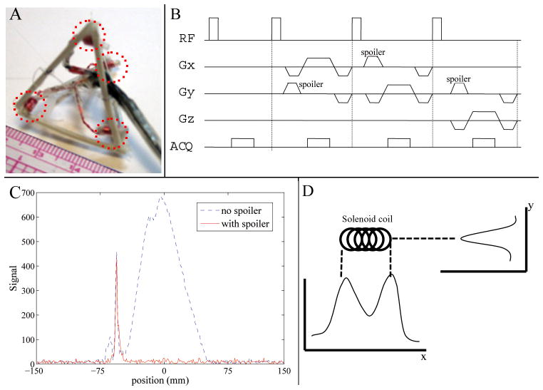
Two mm outer diameter solenoid tracking coils were constructed from hollow PVC piping with a length of 4 mm, 11–40-Gage copper-wire turns, and filled with 20 mL/L Gd-DTPA doped water. Four tracking coils were fixed on to the corners of a tetrahedron at a distance of 3cm from each other (Fig. 1A). The tetrahedron geometry was chosen, because its equilateral design captures the three vectorial (x, y, z) directions equally, and as such provides isotropic resolution of translation and rotation about these directions. Each tracking coil was connected to an independent MRI receiver channel, allowing simultaneous measurement of its position, from which rigid-body motion was calculated (25,29). Each channel was tuned to 50 ohms and matched to the 1.5T MRI resonance frequency. Coils were also actively decoupled with pin diodes, to enable a high SNR (>3000) at tracking rates of 20 FPS.
Figure 1.
(A) 3cm-diagonal tetrahedron with 4 tracking coils (dotted red lines) on its corners. (B) MR-Tracking sequence. (C) Example of a tracking signal from one tracking coil, with (red solid line) and without (blue dotted line) spoiler gradients employed. (D) Sensitivity profiles of a solenoid coil in two orthogonal (x & y) directions.
Real-time tracking with the Tetrahedron
The location of each coil was detected with a tracking pulse sequence (Fig 1B). To correct for local B0 in-homogeneities, one excitation was performed without a spatial encoding gradient to provide a reference frequency-offset. The subsequent three excitations included a nonselective RF pulse followed by gradient readouts along three orthogonal spatial axes. A spoiler gradient in an orthogonal axis to the readout axis was used to eliminate background signal originating from coupling to the adjacent larger-volume imaging coil, while preserving signal in the localized sensitive region (~100mm3) of the tracking coil (Fig. 1C) (27,29,30).
The coil location along each axis was determined by subtracting the location of the reference-frequency peak from the peak location provided by the Fourier-transformed signal of each of the directionally-encoded profiles. The signal detected by the coil was highly dependent upon the orientation of the coil with respect to the applied readout gradients (27). A single peak was observed if the gradient was applied perpendicular to the tracking coil (Fig. 1D, y direction) while two peaks were observed if the readout gradient was applied along the length of the tracking coil, with each local maximum corresponding to an end of the coil (Fig. 1D, x direction). Rather than finding the location of the maximum signal, the centroid of the coil’s intensity profile was calculated. First, the location Lm of the maximum signal intensity was found, then a window, W, centered at Lm was chosen. The size of the window was set at twice the length of the coil, encompassing all the signals from the coil. The location of the centroid Lc was computed as:
| [1] |
Where S(l)is the signal intensity at location l in the projection. This centroid provides the center of the coil, independent of the applied gradient direction. This characteristic can be illustrated with the peak profile shown in Figure 1D. Along the x direction, a maximum-peak detection algorithm will find the location of either end of the coil, but a slight variation in the signal intensity between the two peaks due to noise can cause fluctuations in the detected coil location. This problem is resolved using the centroid algorithm, which always finds a peak location that is a closer approximation to the coil’s center, offering greater robustness and accuracy, even when the tracking peak has a complex profile.
The positions of the 4 tracking coils can be written as a 3×4 matrix X, with columns denoting the position of one coil{mα= (xα, yα, zα)}, α= 1,…,4. The motion parameters can be calculated from these 4 tracking coils:
| [2] |
Where X0 and Xt denote the positions of the tracking coils at time zero and time t (denoted as tracking(ref) and tracking(t) in Fig. 2). Rm is a 3×3 othornormal rotation matrix. Tm is a 3×4 translation matrix, each column of which is the translation vector tm. A closed-form solution for Eq. 2 is determined from the correlation matrix (31,32)
Figure 2.
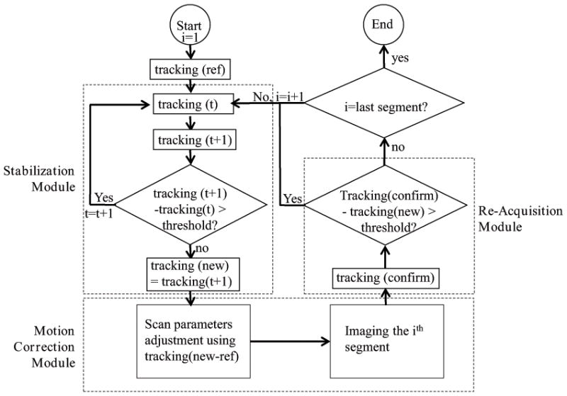
Flow-chart of the motion tracking and prospective motion correction platform used for 2D GRASS. It consists of a Stabilization module which uses tracking for detecting quiet physiological regions, a Motion Correction module for applying prospective motion correction to the imaging sequence, and a Re-Acquisition module for detecting intra-imaging motion, which governs whether the acquired segment will be accepted or rejected and later reacquired.
| [3] |
Where each column of X̄0 and X̄t are the mean vector m̄0 and m̄t respectively. And the mean vector is calculated as:
| [4] |
After decomposing C with singular value decomposition (SVD) into C= UDVT, rotation Rm is:
| [5] |
Translation tm is:
| [6] |
Acquired MR-tracking signals from each coil were processed at a speed of 50 ms (including signal acquisition and processing) to determine the tracking coils’ position and orientation. The processing was performed on a Linux-based operating system, which communicated with the MRI scanner via the RT-Hawk rapid Transmission Control Protocol and Internet Protocol (TCP/IP) connection (33). The resulting motion parameters were then provided to the MRI scan control computer in order to adjust the subsequent imaging segment’s parameters in real-time.
Evaluation of Tracking Accuracy and Precision
The tetrahedron tracking array was attached to an MRI-compatible 3-axis stage (Velmex, East Bloomfield, NY) to test tracking accuracy and precision. This stage could be manually moved in three orthogonal directions independently, at an accuracy of 0.1mm in each direction. The stage holder was placed on the table, so that the vertical axis of the stage was aligned with the Y (anterior-posterior for a patient in head first supine position) axis of the scanner. The two horizontal axes, X (left-right) and Z (superior-inferior) of the stage, were visually aligned with the MRI’s positioning laser marker. After alignment, the holder was tightly fixed to the table for the duration of the experiment. The stage was manually moved along the 3 axes for known distances within a 45 mm range, with the tracking coils measuring the instantaneous locations. At each location, approximately 20 tracking-coil measurements were performed, so that the precision could be calculated. The discrepancy between the known and measured distances provided the accuracy of the tracking coils. The MR tracking parameters were: TR/TE/θ = 7.5ms/3ms/5°, 300 mm FOV, ±32 KHz bandwidth, 256 matrix, providing a resolution of 1.2x1.2x1.2mm at 20 FPS. The small flip angle was applied to minimize changes in spin magnetization for imaging.
The rotational accuracy was simulated using the error measurements from translation, due to the lack of an accurate rotational motion stage. A tetrahedron with 3cm long edges was simulated as rotating around its 3 axes at different angles within a range of 20°. Gaussian noise was added to the position of each corner of the tetrahedron. The rotations were then calculated based on the noisy data and compared with the known angles, with the ensuing discrepancy between the two providing the rotational accuracy. For each angle simulation, 1000 noise values were simulated, from which the precision was calculated.
Prospective motion correction for 2D GRASS
A 2D gradient recalled sequence (GRASS) was modified to integrate prospective motion correction based on the tetrahedron tracking, by placing a tracking sub-sequence in front of each GRASS phase-encoding segment. Three main modules (Fig. 2) were integrated into the GRASS sequence, a Stabilization module, a Motion-Correction module, and a Re-acquisition module. At the start of the acquisition, the positions of the tracking coils were measured and used as references (“ref”) for the relative motion calculations during the scan.
The Stabilization module was intended to improve image quality. When the tracking segment detected large or high-temporal-rate motion, the tracking segment was repeated until the measured motion fell below a preset threshold (i.e. 1mm in X/Y/Z direction), meaning the motion is reaching a relatively stable period. This increased image quality, since imaging was not performed during severe motion periods, which would have contributed only blurred data. The last position of the tracking coils in this module was recorded as the “new” position and it was sent to the scan control computer to correct for relative motion in real-time. The thresholds are currently set only for the three translations, but not for rotations, since the physiological motion (e.g. twisting or beating heart) that occurs during intra-cavity imaging always contains a translational component. Therefore, this is a quick way to judge the degree of motion.
The Motion-Correction module was used for geometric adjustment of the imaging segment. Prior to each imaging segment, motion parameters coming from the tracking computer, “new-ref”, were updated in the pulse sequence through RT-Hawk. Inter-segment relative motion was therefore corrected prospectively for every imaging segment. To correct for rotation, the gradient rotation matrix was adjusted; to correct for translation in the slice selection and read-out direction, the RF transmit and receive frequencies were adjusted, respectively; to correct for translation in the phase-encoding direction, the receiver phase was adjusted.
The Re-acquisition module added robustness to the prospective motion correction system. This module repeated the coil position measurement after each scan segment. The tracking locations acquired after the imaging segment (“confirm”) were compared with the ones obtained before the segment (“new”). If the difference (“confirm-new”) exceeded a preset threshold, this indicated that motion had occurred during this acquisition period, so the acquired k-space lines in this segment were discarded, and the same k-space segment was re-acquired. Otherwise, the scan progressed to the next imaging segment, continuing until the entirety of k-space was filled.
Prospective motion correction for ECG-gated 3D IR-FGRE
A 3D ECG-gated Inversion Recovery spoiled Fast Gradient Echo (IR-FGRE) sequence was modified by adding the tracking segments for motion correction. IR-FGRE was chosen because it is used for cardiac Myocardial Delayed Enhancement (MDE) imaging, as well as for T1-weighted imaging. ECG-gated 3D-MDE was performed with an inversion-recovery pulse, followed by a segmented k-space gradient-echo acquisition (Data Acq segment, Fig. 3), which was triggered to start at the mid-diastolic cardiac phase. In each RR interval, two tracking segments were added to the MDE sequence, one preceding and one following the imaging segment. The tracking-coil position at the beginning of the scan was set as the baseline. During imaging, the position detected by the RR interval’s first tracking segment was compared with the baseline, which provided the encountered motion for use in prospective motion correction of the subsequent imaging segment, similarly to the Motion Correction module’s implementation in 2D-GRASS. The positions detected by the 2nd tracking segment were compared with the 1st segment (translational difference in each direction was calculated), and if any difference was larger than a set threshold, the previously acquired data was rejected, and re-acquired.
Figure 3.
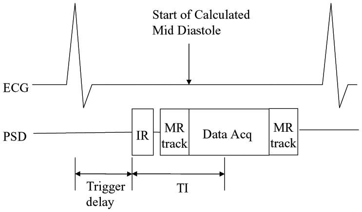
Modified 3D ECG-gated IR-FGRE with an integrated MR-tracking sub-sequence. Acquisition was performed in mid-diastole. Two tracking segments (MR track) were added; before and after the imaging segment, and used to prospectively correct motion for the imaging segment (Data Acq), and to determine the acceptance or rejection of the acquired data.
Experiments for 2D prospective motion correction
Experiments were performed on a GE (Waukesha, WI) 1.5T scanner running 12.x software. The tetrahedron tracking array was fixed tightly to a 5-inch imaging coil, so that during the experiments, the assembly moved with the same motional pattern. This setup mimicked a tracking coil array integrated with an intra-cavity coil. The experiments tested the feasibility of prospective motion correction based on tracking coils which moved along with their adjacent imaging coils.
2D prospective motion correction experiments were performed on ex-vivo swine hearts, which were placed in a water-filled bottle. The bottle sat on the MRI table, which was cyclically displaced by 10mm in the Z direction, interspersed by motionless periods. Rotation was performed using a wooden “Lazy-Suzy table”, using a rod with one end connected to the Lazy-Suzy plate, and the other end connected to the stationary base of the table, so that when the table top moved in and out of the magnet, the phantom on the Lazy-Suzy table translated in-out while rotating around the axis of the Lazy-Suzy table by up to 30°. 2D GRASS parameters: TR/TE/θ= 50/7ms/30°, ±32 KHz bandwidth, 3mm slice thickness, 256×224 matrix, 150x150mm FOV. The thresholds set in both the Stabilization and Re-acquisition Modules were 1mm for translation.
Reference images were acquired without table motion occurring. When motion was performed, scans with and without prospective motion correction were acquired. The images were compared with the reference images. 1D correlation along a line that passes through high-resolution features of the images was used as a quantitative measurement of the image quality.
Experiments for ECG-gated 3D prospective motion correction
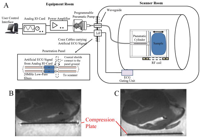
The ECG-gated 3D IR-FGRE experiments were performed with an electro-mechanical heart simulator, developed to allow programmable compression/de-compression of ex-vivo swine heart as well as synchronization of ECG-triggered imaging sequences (Fig. 4A). The simulated cardiac motion is non-rigid during extensive portions of the R-R cycle. The simulator consisted of (1) a modified pneumatic roller pump (Stockert, Munich, Germany), which allowed for programmable bi-directional water flow control, (2) an analog IO card (National Instruments USB-6009, Austin, TX) connected to the pump at one end and to the controlling computer at the other end, (3) a heart compression chamber for placement of an ex-vivo heart, and (4) a 10-meter pneumatic hose. The programmable water pump was placed outside the scanner room, with a water line passing through the scanner-room’s waveguide to the compression chamber, which was located at the scanner’s iso-centre. A LabView software control interface (National Instruments, Austin, TX) was developed to regulate the chamber compression cycle, providing a range of 20–60 beats-per-minute (BPM) speed, a 0–50mm traveling distance, and a 0–25N compression force. The analog-IO card sent out high/low TTL signals to control the clockwise or counterclockwise rotation of the roller pump, which translated to compression or de-compression of the chamber.
Figure 4.
(A) Diagram of the electro-mechanical heart simulator. (B) Compressed heart in the chamber during a simulated systolic phase. (C) De-compressed heart in the chamber during a simulated diastolic phase.
During the simulated cardiac systolic phase, the analog-IO card sent out an artificial ECG QRS complex, which passed through an RF Low-pass filter (DC-22MHz, Mini-circuits, Brooklyn, NY) at the penetration panel to trigger the scanner’s ECG synchronization unit. A high TTL signal, generated at the R-wave peak, triggered the pump to rotate in a clockwise direction, compressing the heart chamber, mimicking left ventricular contraction during the systolic phase (Fig. 4B). During the simulated diastolic phase, a low TTL signal was sent, commanding the pump to rotate counterclockwise to de-compress the chamber, and relaxing the heart tissue to its original shape (Fig. 4C). As a result, complete cardiac cycles were simulated, along with precise ECG triggering.
Respiratory motion was simulated by the MRI table moving 10mm in the Superior/Inferior direction. This translational respiratory motion was not synchronized with the ECG trigger from the analog-IO card. As a consequence, the ex-vivo heart moved with two independent motions, mimicking respiratory and cardiac motion.
The heart was inserted into the sample chamber, which was filled with water doped with 20 mL/L gadolinium-DTPA, mimicking an MDE scan. The diastolic imaging window for the 3D IR-FGRE acquisition was determined by acquiring a segmented k-space, RF-spoiled time-resolved (CINE) 2D FGRE scan (Fig. 4C). The imaging window for the MDE scan was chosen to occur when the heart was fully relaxed. The simulated respiratory motion was detected by the tracking coils, and used for motion correction.
IR-FGRE scan parameters; TR/TE/TI/θ= 4.4ms/2.1ms/200ms/25°, ±62KHz bandwidth, 3mm slice thickness, 256×224 matrix, 180x180mm FOV, 20BPM Heart Rate, triggering delay 1600ms post-QRS (measured from CINE), with the in-plane phase-encodings per slice acquired over 3 R-R cycles. The threshold set in the Re-acquisition Module was 1mm. Images acquired without the simulated respiratory motion were used as references, and motion corrected images acquired with respiration were compared with those references. A 1D correlation along a line that passes through high-resolution features of the images was also used as a quantitative measurement of image quality.
Human Experiment with respiration gating using Tracking coils
To test the combined imaging and tracking assembly in humans, we placed the tetrahedron tracking coil array on top of a human abdomen and used the array to track respiratory motion and gate the acquisition. A surface imaging coil was tightly connected to the tracking coil for imaging at the level of the kidney. The ECG-gated 3D IR-FGRE sequence was used for this experiment, but the motion detected prior to the imaging segment was not used for motion correction, but only for acquisition gating. Motion correction was not performed, since the tracking coils measured surface abdominal motion, but not the actual kidney motion. These motions are correlated, but not in the same direction or amplitude, so accurate motion parameters were not acquired for motion correction. However, respiratory gating could be achieved with the tracking coils and used to test the feasibility of motion correction.
A tracking-only period was executed to find the motion-acceptance window at the subjects’ end-exhalation period, similarly to the strategy applied in respiratory-navigator-gated sequences. Scan parameters; TR/TE/TI/θ=2.7ms/1.1ms/200ms/25°, ±62KHz bandwidth, 3mm slice thickness, 128×128 matrix, 420x420mm FOV, with the in-plane phase encodings per slice acquired over 3 R-R cycles. The studies were performed on five healthy volunteers. All human studies were performed with institutional review board approval and with informed consent.
Results
Tracking Accuracy and Precision
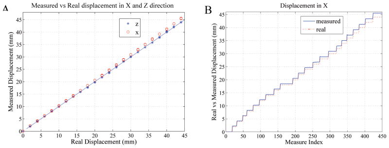
The discrepancy (mean ± standard deviation) between the known movement of the stage and the tracking coils’ measured motion was 0.7±0.5mm, 0.6±0.4mm, 0.1±0.1mm in the X, Y and Z directions, respectively.
Fig. 5A compares the real and measured displacements in the X and Z directions. In the 45mm measurement range, the tracking coils measured Z values matched very well with the true values, as seen by all the points lying along the diagonal line. However, the X direction tracking measurements showed increasingly greater deviations from the diagonal line as the absolute displacements increased, which is well illustrated in Fig. 5B. The Y results were similar to the X (not shown).
Figure 5.
(A) Tracking-coil measured versus actual displacements along the X (o) and Z (*) directions. The diagonal line denotes the zero error line. (B) Measured and actual displacements along the X direction
Gaussian noise with mean and standard deviation 0.7±0.5mm was added to the locations of each corner of the tetrahedron to investigate the accuracy of rotations. In the range of 20°, the rotation accuracy was 0.8° ±0.6° (only rotational accuracy around X is reported here because rotational accuracy around the other two axes is similar).
Prospective motion correction for 2D GRASS
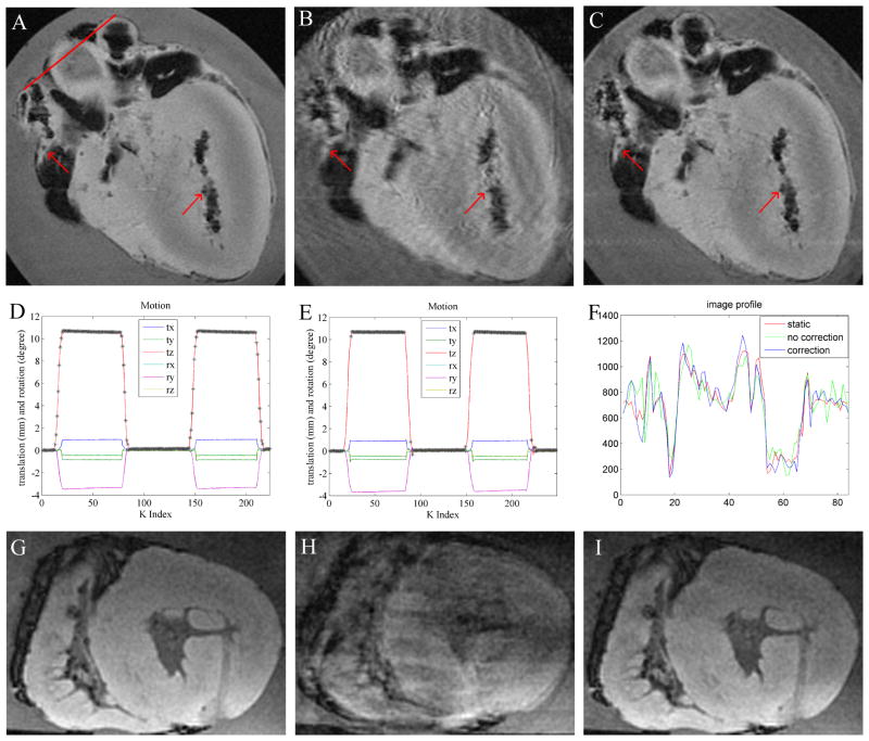
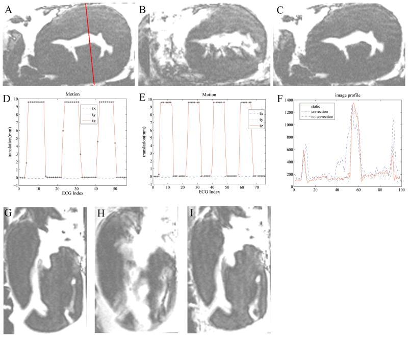
Fig. 6A–C shows an ex-vivo in-plane heart motional experiment. The motional amplitudes observed during scans with and without correction (Fig. 6D, E) were similar. When motion correction was not performed (Fig 6D), all the data acquired during the scan duration was utilized for reconstruction, which led to substantial motion artifacts appearing in the image (Fig. 6B). On the contrary, when prospective motion correction was performed (Fig. 6E), only data acquired during relatively stable periods was accepted. The data was rejected during the rapidly moving periods (e.g. during the rising and falling periods), because during those periods, the k-space data was contaminated by rapid motion, which could not have been corrected. As a result of the reacquisitions, the motion-corrected-scan time (Fig. 6C) was 8% longer, relative to static or non-corrected imaging (Fig. 6A, B). The corrected image quality (Fig. 6C) was much better than when correction was not applied (Fig. 6B). Using the drawn line (Fig. 6A), the corresponding profiles (Fig. 6F) showed that the corrected case preserved nicely both shape and edges, while the uncorrected case did not. The correlation between motion-corrected and the static profile was 0.96, as compared with only 0.88 between the motion-uncorrected and the static profile. Through-plane motion corrections were also performed, (Fig 6. G–I), with similar observed improvements in image quality.
Figure 6.
Prospective 2D GRASS motion correction in a moving ex-vivo swine heart using tetrahedral-array MR-tracking. In-plane motion correction; (A) stationary image; (B) moving without correction; (C) moving with correction; red arrows highlight details corrupted by motion in (B). Black areas in the images correspond to air-filled regions. (D,E) Motional pattern detected with the tracking coils, during the acquisition of images (B,C) respectively. tx,ty,tz denote translation, and rx,ry,rz denote rotation along the respective directions. ‘*’ marks accepted positions. In the non-corrected case (D), all points are accepted, while in the corrected case (E), only points without rapid motion are accepted. (F) is a profile across the red line drawn through (a) in the 3 images. (G–I) Prospective through-plane motion correction (motionless (G), moving without correction (H), moving and corrected (I)).
Prospective motion correction for ECG-gated 3D IR-FGRE
Simulated respiratory motion during a 3D-IR-FGRE scan was studied (Fig. 7) with table motion occurring mainly along the Z direction. In-plane motion correction experiments were first carried out (Fig. 7A–C). When motion correction was not applied, acquisition was continuously performed, including while the ex-vivo heart moved rapidly, as well as when it displaced from the reference position by 10mm distance, which resulted in large motion artifacts (Fig. 7B). With motion correction enabled (Fig. 7C), acquisitions during periods of fast motion were discarded. Only points acquired during the low and high positional movement plateaus were accepted, and motion correction was performed to include these two segments. Profiles along a line (Fig. 7F) demonstrate that with respiratory motion correction, the profile with correction closely matches the static profile. The correlation between the corrected profile and the static profile was 0.97, and 0.72 between the uncorrected profile and the static profile. The experiments (Fig. 7G–I), with table motion occurring primarily in the through-plane direction, demonstrate similar motion-correction improvements.
Figure 7.
Prospective 3D ECG-gated IR-FGRE motion correction in a moving ex-vivo swine heart using tetrahedral-based tracking during simulated respiratory motion. (A–C) In-plane respiration correction, (A) stationary image; (B) moving without correction; (C) moving with correction. (D,E) Motional pattern detected with the tracking coils corresponding to the images (B,C) respectively. tx,ty,tz denotes translation in the respective directions. ‘*’ marks accepted positions. Non-corrected case (D) accepts all points, while corrected case (E) accepts only points with no rapid motion. (F) is a profile across the red solid line drawn through (a) in the 3 images. (G–I) Through-plane respiratory motion correction experiment; stationary (G) moving without correction (H) and moving with correction (I).
Human Experiment with Tracking coils gating the respiration
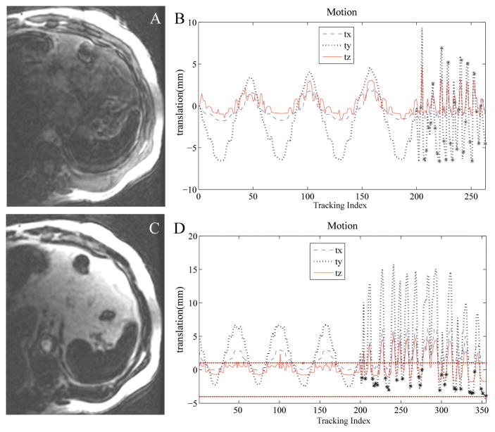
The human 3D-IR-FGRE abdominal experiment acquired free-breathing images (Fig. 8) without (A) and with (C) respiratory gating using the tracking coil array. A tracking-only period (first 200 time points in both Fig. 8B, D) was executed to find the motion-acceptance window at the subject’s end-exhalation period. The acquisition of 3D-IR-FGRE started right after the tracking-only period. But because the tracking was performed at a much lower frame rate (instead of continuous tracking at 20 FPS, it was only run twice in one RR interval), the motion pattern after 200 time points was not smooth. When no respiratory gating was applied, the acceptance window was not used to gate the acquisition, as shown in Fig. 8B and all k-space 3D-IR-FGRE data were accepted. Considerable image quality improvement was observed when gating was performed with an acceptance window of 5mm around end-exhalation (Fig. 8C). The breathing motion magnitude was approximately 10mm, which caused substantial motion artifacts when gating was not performed and all imaging data were accepted (Fig. 8A). The improved image quality in Fig. 8C was obtained with 155 total acquired imaging segments (Fig. 8D) versus only 63 segments without correction (Fig. 8B). The 92 extra acquired segments were determined to be above the 5mm threshold and were all discarded and reacquired.
Figure 8.
3D IR-FGRE experiment to image the human kidney with respiratory gating using a tracking coil array placed on the abdomen together with an imaging coil. (A) without respiratory gating, (B) motion recorded with the tracking coils prior to and during the acquisition of (A). The first 200 time points show the tracking only period, and show a continuous breathing pattern, while the points after index 200 are during IR-FGRE image acquisition and show a discrete pattern due to the slower sampling rate. “*” marks the accepted points, which are all points when respiratory gating is not applied. (C) Imaging with respiratory gating, and (D) the motion recorded prior to and during the course of acquiring (C). Dotted horizontal lines show the 5mm acceptance window.
Discussion
MRI imaging using intra-cavity coils offers better SNR relative to surface coils which in turn can lead to higher resolution images and improved diagnosis. However, because intra-cavity coils touch the imaged anatomic features of interest, the coils frequently move together with them when physiological motion occurs. As a result, motion artifacts are created which can substantially degrade the acquired images. In this study, we overcame these motion artifacts by integrating tracking coils with imaging coils.
MR-tracking coils offer several advantages. First, they are small and easily integrated into the intra-cavity probe without expanding the footprint of the imaging coils. MR-tracking coils can be made as small as 0.1mm in diameter. We have previously used 1mm diameter coils for coronary motion tracking (35). Reducing coil size reduces the SNR efficiency (SNR/√time), so either the tracking frame rate or the spatial resolution may have to be reduced. Second, MR tracking has sub-millimeter accuracy and precision. Our measurements have provided their accuracy at both the center of the bore (the Z results) as well as the edges of the magnet’s usable sweet spot (the X and Y results). It is clear that even when the gradients are less linear, the coils can be used for motion correction. These features are essential for prospective motion correction, which requires that the actual amplitude of motion be corrected, while only a minimal degree of noise is introduced into the acquired k-space. Third, the MR tracking process is fast. 3D position localization can be performed at 20 FPS. Fourth, the microcoils track local internal motion, a task which cannot be achieved with external tracking devices (e.g. optics), so the coils are well-suited for intra-cavity coil motion correction.
Prospective motion correction substantially improved image quality in both 2D and 3D imaging, for both the in-plane and through-plane motion. Because scan parameters were adjusted in real-time to follow the motion, the images were acquired in the anatomic frame of reference, so that at the end of the scan only good data were recorded, and conventional (on-line) image reconstruction was performed. The images were reconstructed and appeared on the console immediately after acquisition, unlike retrospective motion correction requiring off-line reconstruction.
We tested the absolute MR-tracking accuracy with an MR-compatible stage. Within a 45mm range, the absolute errors in X and Y were comparable, but were larger than observed along Z. Since our tracking coils were in a symmetric tetrahedron shape, the errors in all directions were expected to be similar. A likely cause of the directional differences observed is gradient non-linearity. The stage placed the tracking coils close to the top right of the magnet bore (approximately 20cm from iso-center in X and Y, but centered along the Z axis). In this region the gradients in the X and Y direction are more non-linear than in the Z direction. It is clear, that for more accurate displacement and rotational corrections away from isocenter, the tracking positions will have to be corrected for gradient distortions.
Rotation simulations showed that the error was less than 1° with a 3cm diagonal tetrahedron. Using the same simulation and noise level, this error increased to 2.2° ±1.7° when the tetrahedron was reduced to 1cm on diagonal, and decreased to 0.5° ±0.3° if the tetrahedron was enlarged to 5cm diagonals. This suggested that the size of the tetrahedron should be constructed to be as large as possible, while still fitting within the desired body cavity for better rotational accuracy. To allow the deployment of a large tetrahedron into a body cavity, a folding apparatus was designed and implemented. A 2cm intra-cardiac coil, folded onto a catheter shaft, so that during vascular deployment it had a 4mm outer diameter, while when unfolded in the heart it reached a 2cm diagonal size, has been developed. This catheter assembly will be tested in animals in the near future (34).
We developed an electro-mechanical heart stimulator for the ECG-gated 3D-IR-FGRE experiment, where the ex-vivo heart independently underwent simulated cardiac and respiratory motion. The motion induced, however, was still somewhat simplified relative to actual cardiac motion. In reality, respiration causes not only a Superior-Inferior shift of the heart, but also a non-rigid deformation of the heart, which becomes important during a large displacement of the diaphragm. As shown in Fig. 7E, both the 0mm (simulating peak expiration) and 10mm (simulating peak inspiration) plateaus’ data were accepted when motion correction was performed. For human experiments, the 10mm data should be rejected, since peak inspiration would surely lead to heart deformation relative to the heart’s shape at peak expiration. Therefore, a reasonable acceptance window to ensure negligible deformation of the heart needs to be determined.
Human volunteer experiments demonstrated that tracking coils provided accurate motion detection, allowing respiratory gating when placed on the abdomen with a surface coil. This suggests that motion correction may be feasible, once tracking coils are integrated with intra-cavity coils, since it measures directly the motion of the internal imaging targets. Comparing the acceptance rates in motion correction (Figs. 6 and 7) with gating (Fig 8), it is seen that gating alone led to less efficient scans than prospective correction. When gating was used, data were accepted only if the imaging target moved within a small acceptance window, such as the 5mm window used in the human experiment. When motion correction was used, however, motion was followed and corrected in real-time, so in theory, no acceptance window needed to be set, as seen in Fig. 6E & 7E where both 0 and 10mm positions were accepted. In practice, however, an acceptance window may be required due to the tissue deformation. Nevertheless, the size of the acceptance window could be larger to gain efficiency.
For all the experiments, only translational thresholds were set, due to the fact that physiological motion always contains at least one translational component, but if pure rotational motion is to be corrected (e.g. patient rolling), rotational thresholds can be easily added.
In our experiments, the tracking coils moved together with the imaging coil. However outside the ex-vivo heart, artifacts still remained despite motion correction (Figs. 6, 7). Using Fig. 7I as an example, prospective motion correction dramatically recovered the heart tissue image quality, but relative to Fig. 7G, artifacts outside of the heart are observed. This was caused due to water flow in the chamber which occurred each time the table moved relative to the chamber, and could not be corrected. This suggests that in in-vivo imaging, the imaging target’s appearance will improve, while the neighboring organs, which move at a different rate and in a different direction, might receive enhanced motion artifacts and appear blurred. This, however, is likely to be inconsequential for intra-cavity coil imaging, given the small size of the imaging coil and highly localized imaging-sensitivity.
In conclusion, we developed prospective motion correction techniques for intra-cavity imaging using an array of tracking coils. Although not used in intra-cavity imaging in this paper, this preliminary work has shown that the tracking coils are accurate and fast enough to provide motion information in high-resolution imaging.
Acknowledgments
This study was supported by NIH P41 RR019703, R01 CA11288, R01 CA111981-01, as well as AHA 10SDG261039.
References
- 1.Bock M, Wacker FK. MR-guided intravascular interventions: Techniques and applications. Journal of Magnetic Resonance Imaging. 2008;27(2):326–338. doi: 10.1002/jmri.21271. [DOI] [PubMed] [Google Scholar]
- 2.Hillenbrand CM, Elgort DR, Wong EY, Reykowski A, Wacker FK, Lewin JS, Duerk JL. Active device tracking and high-resolution intravascular MRI using a novel catheter-based, opposed-solenoid phased array coil. Magnetic Resonance in Medicine. 2004;51(4):668–675. doi: 10.1002/mrm.20050. [DOI] [PubMed] [Google Scholar]
- 3.Hurst GC, Hua J, Duerk JL, Cohen AM. Intravascular (catheter) NMR receiver probe: Preliminary design analysis and application to canine iliofemoral imaging. Magnetic Resonance in Medicine. 1992;24(2):343–357. doi: 10.1002/mrm.1910240215. [DOI] [PubMed] [Google Scholar]
- 4.Ladd ME, Quick HH, Debatin JF. Interventional MRA and intravascular imaging. Journal of Magnetic Resonance Imaging. 2000;12(4):534–546. doi: 10.1002/1522-2586(200010)12:4<534::aid-jmri4>3.0.co;2-q. [DOI] [PubMed] [Google Scholar]
- 5.Quick HH, Ladd ME, Zimmermann-Paul GG, Erhart P, Hofmann E, Schulthess GKv, Debatin JF. Single-loop coil concepts for intravascular magnetic resonance imaging. Magnetic Resonance in Medicine. 1999;41(4):751–758. doi: 10.1002/(sici)1522-2594(199904)41:4<751::aid-mrm14>3.0.co;2-v. [DOI] [PubMed] [Google Scholar]
- 6.Martin JF, Hajek P, Baker L, Gylys-Morin V, Fitzmorris-Glass R, Mattrey RR. Inflatable surface coil for MR imaging of the prostate. Radiology. 1988;167:268–270. doi: 10.1148/radiology.167.1.3347731. [DOI] [PubMed] [Google Scholar]
- 7.Zhang JQ, Loughlin KR, Zou KH, Haker S, Tempany CMC. Role of Endorectal Coil Magnetic Resonance Imaging in Treatment of Patients with Prostate Cancer and in Determining Radical Prostatectomy Surgical Margin Status: Report of a Single Surgeon’s Practice. Urology. 2007;69(6):1134–1137. doi: 10.1016/j.urology.2007.01.094. [DOI] [PMC free article] [PubMed] [Google Scholar]
- 8.Baudouin CJ, Soutter WP, Gilderdale DJ, Coutts GA. Magnetic resonance imaging of the uterine cervix using an intravaginal coil. Magnetic Resonance in Medicine. 1992;24(1):196–203. doi: 10.1002/mrm.1910240123. [DOI] [PubMed] [Google Scholar]
- 9.Sarty GE, Baerwald AR, Loewy J, Pierson RA. Canadian Association of Radiologists Journal. Vol. 56. Elsevier Science; 2005. Externally Placed vs Intravaginally Positioned Radio Frequency Coils for Quantitative Spin-Spin Relaxometry of Ovarian Follicular Fluid; pp. 40–47. [PMC free article] [PubMed] [Google Scholar]
- 10.Dick AJ, Guttman MA, Raman VK, Peters DC, Pessanha BSS, Hill JM, Smith S, Scott G, McVeigh ER, Lederman RJ. Magnetic Resonance Fluoroscopy Allows Targeted Delivery of Mesenchymal Stem Cells to Infarct Borders in Swine. Circulation. 2003;108(23):2899–2904. doi: 10.1161/01.CIR.0000095790.28368.F9. [DOI] [PMC free article] [PubMed] [Google Scholar]
- 11.Lederman RJ, Guttman MA, Peters DC, Thompson RB, Sorger JM, Dick AJ, Raman VK, McVeigh ER. Catheter-Based Endomyocardial Injection With Real-Time Magnetic Resonance Imaging. Circulation. 2002;105(11):1282–1284. doi: 10.1161/01.CIR.0000012425.71261.FC. [DOI] [PMC free article] [PubMed] [Google Scholar]
- 12.Homagk A-K, Umathum R, Korn M, Weber M-A, Hallscheidt P, Semmler W, Bock M. An expandable catheter loop coil for intravascular MRI in larger blood vessels. Magnetic Resonance in Medicine yr? 63(2):517–523. doi: 10.1002/mrm.22228. [DOI] [PubMed] [Google Scholar]
- 13.Ladd ME, Quick HH. Reduction of resonant RF heating in intravascular catheters using coaxial chokes. Magnetic Resonance in Medicine. 2000;43(4):615–619. doi: 10.1002/(sici)1522-2594(200004)43:4<615::aid-mrm19>3.0.co;2-b. [DOI] [PubMed] [Google Scholar]
- 14.Martin AJ, Henkelman RM. Intravascular MR imaging in a porcine animal model. Magnetic Resonance in Medicine. 1994;32(2):224–229. doi: 10.1002/mrm.1910320211. [DOI] [PubMed] [Google Scholar]
- 15.Quick HH, Ladd ME, Hilfiker PR, Paul GG, Ha S-W, Debatin JF. Autoperfused balloon catheter for intravascular MR imaging. Journal of Magnetic Resonance Imaging. 1999;9(3):428–434. doi: 10.1002/(sici)1522-2586(199903)9:3<428::aid-jmri10>3.0.co;2-e. [DOI] [PubMed] [Google Scholar]
- 16.Choi YJ, Kim JK, Kim N, Kim KW, Choi EK, Cho K-S. Functional MR Imaging of Prostate Cancer. Radiographics. 2007;27(1):63–75. doi: 10.1148/rg.271065078. [DOI] [PubMed] [Google Scholar]
- 17.Schnall MD, Lenkinski RE, Pollack HM, Imai Y, Kressel HY. Prostate: MR imaging with an endorectal surface coil. Radiology. 1989;172(2):570–574. doi: 10.1148/radiology.172.2.2748842. [DOI] [PubMed] [Google Scholar]
- 18.Tempany C, Straus S, Hata N, Haker S. MR-guided prostate interventions. Vol. 27. Wiley Subscription Services, Inc., A Wiley Company; 2008. pp. 356–367. [DOI] [PMC free article] [PubMed] [Google Scholar]
- 19.Heijmink SWTPJ, Futterer JJ, Hambrock T, Takahashi S, Scheenen TWJ, Huisman HJ, Hulsbergen-Van de Kaa CA, Knipscheer BC, Kiemeney LALM, Witjes JA, Barentsz JO. Prostate Cancer: Body-Array versus Endorectal Coil MR Imaging at 3 T- Comparison of Image Quality, Localization, and Staging Performance. Radiology. 2007;244(1):184–195. doi: 10.1148/radiol.2441060425. [DOI] [PubMed] [Google Scholar]
- 20.Ehman RL, Felmlee JP. Adaptive technique for high-definition MR imaging of moving structures. Radiology. 1989;173(1):255–263. doi: 10.1148/radiology.173.1.2781017. [DOI] [PubMed] [Google Scholar]
- 21.van der Kouwe AJ, Benner T, Dale AM. Real-time rigid body motion correction and shimming using cloverleaf navigators. Magn Reson Med. 2006;56(5):1019–1032. doi: 10.1002/mrm.21038. [DOI] [PubMed] [Google Scholar]
- 22.Fu ZW, Wang Y, Grimm RC, Rossman PJ, Felmlee JP, Riederer SJ, Ehman RL. Orbital navigator echoes for motion measurements in magnetic resonance imaging. Magn Reson Med. 1995;34(5):746–753. doi: 10.1002/mrm.1910340514. [DOI] [PubMed] [Google Scholar]
- 23.Welch EB, Manduca A, Grimm RC, Ward HA, Jack CR., Jr Spherical navigator echoes for full 3D rigid body motion measurement in MRI. Magn Reson Med. 2002;47(1):32–41. doi: 10.1002/mrm.10012. [DOI] [PubMed] [Google Scholar]
- 24.Petrie DW, Costa AF, Takahashi A, Yen YF, Drangova M. Optimizing spherical navigator echoes for three-dimensional rigid-body motion detection. Magn Reson Med. 2005;53(5):1080–1087. doi: 10.1002/mrm.20445. [DOI] [PubMed] [Google Scholar]
- 25.Qin L, Gelderen Pv, Derbyshire JA, Jin F, Lee J, Zwart JAd, Tao Y, Duyn JH. Prospective head-movement correction for high-resolution MRI using an in-bore optical tracking system. Magnetic Resonance in Medicine. 2009;62(4):924–934. doi: 10.1002/mrm.22076. [DOI] [PMC free article] [PubMed] [Google Scholar]
- 26.Schmidt EJ, Mallozzi RP, Thiagalingam A, Holmvang G, d’Avila A, Guhde R, Darrow R, Slavin GS, Fung MM, Dando J, Foley L, Dumoulin CL, Reddy VY. Electroanatomic Mapping and Radiofrequency Ablation of Porcine Left Atria and Atrioventricular Nodes Using Magnetic Resonance Catheter Tracking. Circ Arrhythm Electrophysiol. 2009;2(6):695–704. doi: 10.1161/CIRCEP.109.882472. [DOI] [PubMed] [Google Scholar]
- 27.Dumoulin CL, Mallozzi RP, Darrow RD, Schmidt EJ. Phase-field dithering for active catheter tracking. Magnetic Resonance in Medicine. 2010;63(5):1398–1403. doi: 10.1002/mrm.22297. [DOI] [PubMed] [Google Scholar]
- 28.Dumoulin CL, Souza SP, Darrow RD. Real-time position monitoring of invasive devices using magnetic resonance. Magnetic Resonance in Medicine. 1993;29(3):411–415. doi: 10.1002/mrm.1910290322. [DOI] [PubMed] [Google Scholar]
- 29.Ooi MB, Krueger S, Thomas WJ, Swaminathan SV, Brown TR. Prospective real-time correction for arbitrary head motion using active markers. Magnetic Resonance in Medicine. 2009;62(4):943–954. doi: 10.1002/mrm.22082. [DOI] [PMC free article] [PubMed] [Google Scholar]
- 30.Krueger S, Wolff S, Schmitgen A, Timinger H, Bublat M, Schaeffter T, Nabavi A. Fast and Accurate Automatic Registration for MR-Guided Procedures Using Active Microcoils. Medical Imaging, IEEE Transactions on. 2007;26(3):385–392. doi: 10.1109/TMI.2006.889748. [DOI] [PubMed] [Google Scholar]
- 31.Kanatani K. Analysis of 3-D rotation fitting. IEEE Trans Pattern Analysis and Machine Intelligence. 1994;16(5):543–549. [Google Scholar]
- 32.Umeyama S. Least-squares estimation of transformation parameters between two point patterns. IEEE Trans Pattern Analysis and Machine Intelligence. 1991;13(4):376–380. [Google Scholar]
- 33.Santos JM, Wright GA, Pauly JM. Flexible real-time magnetic resonance imaging framework. Conf Proc IEEE Eng Med Biol Soc. 2004;2:1048–1051. doi: 10.1109/IEMBS.2004.1403343. [DOI] [PubMed] [Google Scholar]
- 34.Schmidt EJ, Qin L, Santos Ju, Michaud GF, Kwong RK, Butts-Pauly K, Stevenson WG, Dumoulin CL. Intra-Cardiac MRI Catheter for EP Ablation Monitoring: Preliminary Studies. Proc Intl Magn Reson Med. 2011:4343. [Google Scholar]
- 35.Schmidt EJ, Yoneyama R, Dumoulin CL, Darrow RD, Klein E, Kiruluta AJ, Hayase M. 3D coronary motion tracking in swine models with MR tracking catheters. J Magn Reson Imaging. 2009;29:86–98. doi: 10.1002/jmri.21468. [DOI] [PubMed] [Google Scholar]


