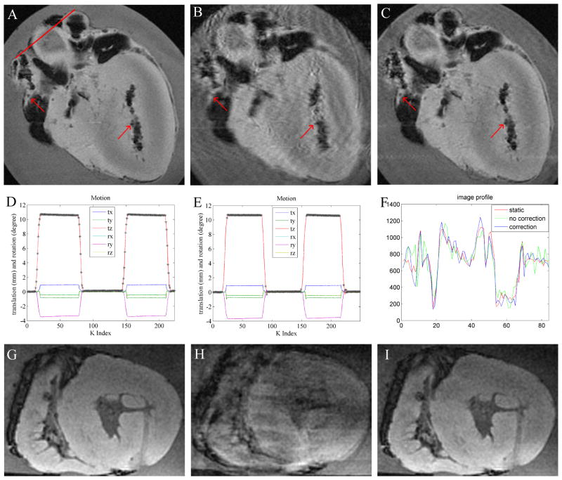
Figure 6.
Prospective 2D GRASS motion correction in a moving ex-vivo swine heart using tetrahedral-array MR-tracking. In-plane motion correction; (A) stationary image; (B) moving without correction; (C) moving with correction; red arrows highlight details corrupted by motion in (B). Black areas in the images correspond to air-filled regions. (D,E) Motional pattern detected with the tracking coils, during the acquisition of images (B,C) respectively. tx,ty,tz denote translation, and rx,ry,rz denote rotation along the respective directions. ‘*’ marks accepted positions. In the non-corrected case (D), all points are accepted, while in the corrected case (E), only points without rapid motion are accepted. (F) is a profile across the red line drawn through (a) in the 3 images. (G–I) Prospective through-plane motion correction (motionless (G), moving without correction (H), moving and corrected (I)).

