Fig. 2.
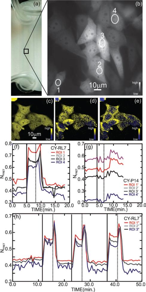
Validation of the CY-RL7 redox sensor in CHO cells. (a) Microfluidic channel showing the tubing used for fluid exchange (left) and CHO cell FRET channel image with the regions of interest (ROI) enumerated (right). (b) Fluorescence micrograph showing CHO cells imaged in the microfluidic channel in a low flow (48 μL min–1) at t = 0, just prior to a diamide pulse (see the corresponding Fig. (f) as well). (c,d,e) Confocal images of CHO cells show that, on exposure to a 1 mM diamide pulse, the spatial distribution and intensity of the FRET signal changes, indicating a change in the redox environment in the cytoplasm. The three confocal images compare (c) the integrated two dimensional projection of the three dimensional confocal image constructed from the change in YFP channel with (d,e) showing slices taken from (c) along the optic axis at z = 0.5 μm and z = 4.5 μm respectively. (f,g) Time lapse of the fluorescence of a few ROIs demonstrates the response of the CY-RL7 and CY-P14 FRET constructs respectively expressed in CHO cells after treatment with 1 mM exogenous oxidant diamide (solid vertical line at t = 5 min) followed by removal of oxidant (dashed vertical line, t = 8 min). The ROIs associated with CY-RL7 shown in (f) are indicated in (b), while the ROIs associated with CY-P14 are taken from other cells not shown. (h) Three sequential cycles, comprised of an oxidative insult with 1 mM diamide (solid vertical lines) followed by removal of oxidant by brief washing (dashed vertical lines) 4 min later, were applied to CHO cells (not shown), illustrating the reversible nature of the CY-RL7 response. The data are representative of 12 independent experiments using a minimum of 4 ROIs.

