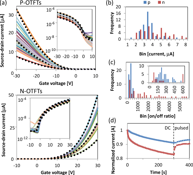
Figure 2.
(a) Transfer characteristics of printed p- and n-channel OTFTs, with channel length of 2.75 mm and width of 35 μm, in saturation regime Vds = ±20 V and Vgs = ±20 V. The dotted lines represent best-fit models for slow, typical, and fast OTFTs. Histograms of current distribution (b) and on/off ratio (c) were taken from measurements in linear regime Vds = ±5 V and Vgs = ±20 V for lower bound estimation. (d) Normalized current during operation with Vds = ±20 V and Vgs = ±20 V at constant gate bias or at pulsed gate bias of 1 kHz, 50% duty cycle.

