
Figure 6.
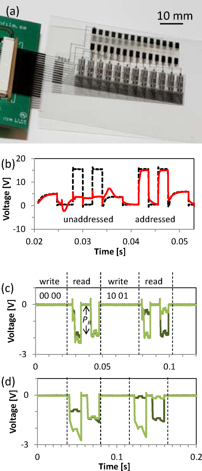
(a) Photograph of a 3-bit decoder circuit and ferroelectric capacitor memory. Four redundant sub-units were included in this photograph for yield improvement. (b) Input (black dotted line) and output (red line) signals through the printed decoder circuit. The output signal follows the input if the decoder sub-unit is addressed, whereas the output signal is floating when the sub-unit is un-addressed. (c) Bit-line signals read from a 2×2 array of memory capacitors patterned by photolithography. The two lines with different shades of green represent two neighboring bit-lines. Remnant polarization PR is indicated by the black arrow. (d) Same as (c) but the memory capacitors were patterned by gravure printing.