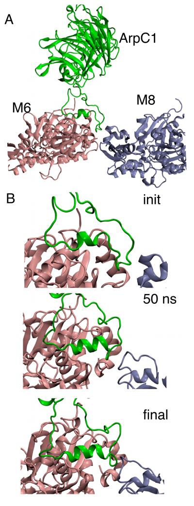
Fig. 6.
Ribbon diagrams showing detailed views of the interface between ARPC1 and the mother filament. The other subunits of Arp2/3 complex and the mother filament are omitted for clarity. (A) Initial configuration of all three subunits from the model based on EM tomography with the loop consisting of ARPC1 residues 288-322 in contact with the mother filament. (B) Close-up views of the ARPC1 loop bound to the mother filament at the initial, 50 ns and final points of the simulation. An additional alpha helical turn in ARPC1 insert helix formed by 50 ns and was very stable after that point. The snapshots shown from Branch08 because it came from a longer simulation time, however the stability of the helix was also observed in Branch10.

