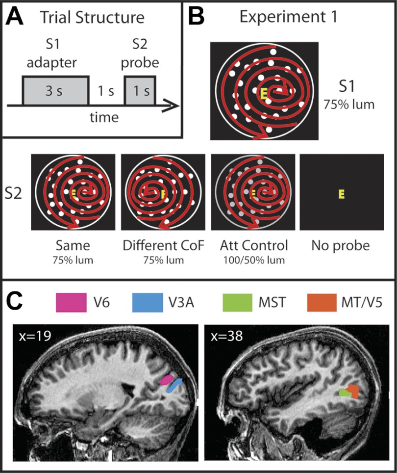
Fig. 1.
Stimuli, experimental design, and anatomical location of regions of interest (ROIs). A: schematic representation of a single trial sequence. The experiment was designed to test for adaptation effects in several motion areas. For that purpose, in every trial a pair of stimuli were presented sequentially. The first stimulus (S1), referred to as the adapter, was shown for 3 s, followed by a 1-s presentation of a black background displaying only a fixation square. After this, the second stimulus (S2), the probe, was presented for 1 s. Trials were separated by 8-s periods of background presentation. B: stimuli. There were 4 conditions: Same (S1 = S2), Different CoF [center of flow (CoF) of S2 located in the opposite left-right location to S1], Attention Control (S2 had the same CoF but a different luminance), and No Probe (no S2). In all trials, the adapter consisted of dots expanding, contracting, and rotating from a CoF located toward the right or left of fixation, as indicated by the red arrows. The arrows and the white circle surrounding the dots were not present in the stimuli and are shown only for diagrammatic purposes. The red arrows indicate only that spiral global motion occurred and do not represent dot trajectories. C: cortical ROIs. The locations of areas V6, V3A, MST, and MT/V5 on sagittal slices of the brain of 1 participant are shown. Slice coordinates are in Talairach space.

