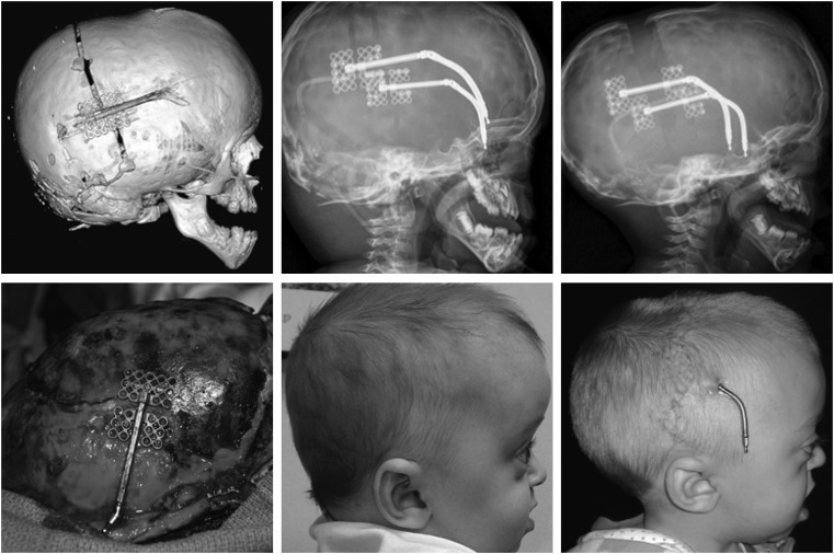
Figure 5.
This figure demonstrates distraction osteogenesis of the posterior cranial vault. The left images are three-dimensional computed tomography and intraoperative views of the osteotomies and distraction device placement. The middle images are radiographic and clinical views prior to distraction; the right images are the same views at the end of the activation phase of distraction osteogenesis. (Reprinted with permission from Steinbacher DM, Skirpan J, Puchala J, et al. Expansion of the posterior cranial vault using distraction osteogenesis. Plast Reconstr Surg 127: 792–801).

