Figure 9.
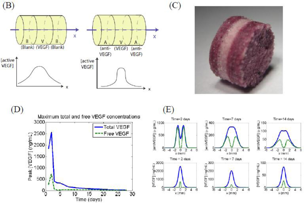
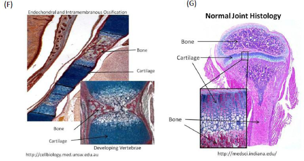
Spatial control of growth factor and inhibitor release to provide tight spatial control over regeneration. The location of factor release and orientation of the scaffold is chosen to create a zone where the regeneration of the tissue is desired. The promoter and inhibitor partially cancel each other’s effects, leading to a sharp cut-off in the spatial location where regeneration is promoted (A). This approach has been shown to be effective in creating an angiogenic zone with high spatio-temporal resolution. Layered scaffolds were made delivering VEGF and Anti-VEGF (B-C). Simulation of concentration profiles of unbound VEGF and total VEGF in the surrounding tissues over time shows initial bursts in both VEGF and antibody, they react quickly and the resulting concentration of active VEGF is significantly lower than the total VEGF in the first two days (D). (E) simulation plots of concentration profiles of anti-VEGF and VEGF at 3, 7, 14, and 21 d in which VEGF and anti-VEGF are regulated to partially cancel each other to enable spatial resolution. During implantation, the orientation of the scaffold was chosen to create an angiogenic zone directly over the section of the femoral artery that was ligated—with a goal of creating new blood vessels that would bypass the ligated vessel. The study showed that using this design, it was possible to create an angiogenic zone of 1mm wide that lasts for 3 weeks. In contrast, no incorporation of the antibody in the side layers resulted in an angiogenic zone that starts out very broadly and shrinks over time. The approach of delivering antagonists may be used in other morphogenic processes where spatial control is important, for example juxtaposed cartilage and bone in spine and limbs (F-G).


